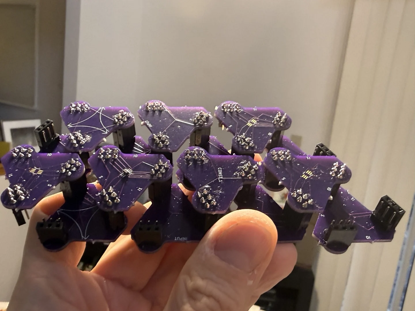
Twenty-Five Years Of Thought Became A Physical Language
The idea moved through mental models, paper, and CAD for roughly twenty-five years. Then the first connectorized batch snapped into a circuit patch that could leave the table as one object.
Symbols became parts whose roles, sides, rotations, and neighbor relationships remain legible after assembly.
The circuit diagram and the manipulable physical representation become the same thing.
Five Roles Form The Alphabet
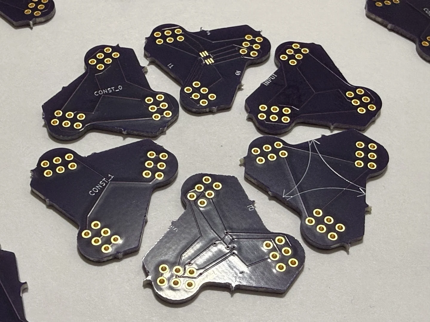
- Input: marks the intended entry role at a visible place in the patch.
- Constants: represent logic zero and logic one as explicit physical roles.
- MUX: shows
I0,I1, selectorS, and the intended output route in one piece. - Wire and routing: represent a path across the patch without hiding topology in a bundle.
- Intersection: represents crossings and connection management in readable space.
Connector Geometry Makes Orientation Real
A schematic leaves orientation to the reader. These tiles encode it through connector sides, contact groups, physical rotation, and neighboring pieces. Turn the assembly in your hand and its topology remains visible from every angle.

Six Steps Carry A Learner From MUX To FPGA
The sequence begins with one physical decision and ends with a circuit that a learner can express as a truth table, Logisim design, or FPGA RTL.
Name The Ports
Find
I0,I1,S, input, constant, and route roles directly on the boards.Predict One Selection
Choose values for the two MUX inputs and selector, then state which physical route should reach the output.
Rotate And Compose
Change the orientation of a piece, identify its new neighbors, and explain what topology changed.
Trace A Value
Follow a constant or input through route and intersection pieces without collapsing the patch back into an invisible netlist.
Build A Combinational Patch
Use several pieces to represent a Boolean function, write its truth table, and reproduce it in Logisim.
Move From MUX To LUT
See how one selector becomes LUT1, how more address bits grow the stored truth table, and how the idea reaches real FPGA LUT4, LUT5, and LUT6 structures.
MUX Algebra supplies the notation and truth tables: one selector becomes a conditional, nested choices cover every LUT2 function, and a four-bit word configures the result.
The Same Selection Rule Reaches FPGA Logic And Cartilage
From Logisim And Multiplexers To LUT1–LUT6 grows the visible 2:1 MUX into a stored truth table, then connects LUT4 to Lattice iCE40 and LUT5/LUT6 to AMD/Xilinx configurable logic.
FPGA And Verilog From First Principles carries the physical selector through Logisim, LUTs, Verilog, a self-checking testbench, synthesis, a bitstream, and a programmed board.
The Cartilage learning path adds CMOS gain, output drive, clock and event distribution, statecharts, one-hot machines, timing closure, metal routing, nested components, and runtime instantiation in adjacent space.
The Fabricated Alphabet Already Composes In Three Dimensions
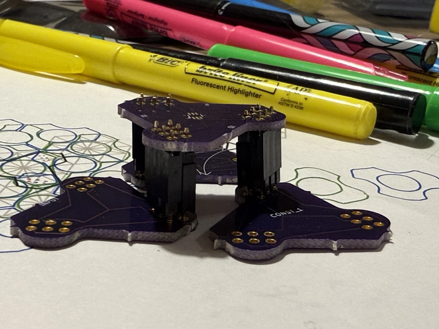
Role variants share one repeated outline. Exposed plated contacts accept socket and header parts. Multiple tiles lock into palm-scale assemblies, and static connector spacing creates more than one elevation.
Powering a D-flip-flop patch will add sequential behavior, timing, signal integrity, and insertion-cycle measurements to the physical language. From there, classroom use and production engineering can grow around the same readable geometry.
Follow The Physical Alphabet From Its First Publication
The Physical MUX Tile Alphabet records the first publication on January 31, 2026. The photographs here show the fabricated roles, connector geometry, and assembled patches at useful scale.
Bring this alphabet into an electrical-engineering classroom, a powered logic build, or a manufacturable learning kit: contact Brian Greenforest.