One Rule Controls Every Circuit
M(S, D0, D1) = S ? D1 : D0
Each lesson connects equation to machine. The clean circuit appears first; the same function follows as a placed and routed Cartilage fabric. A pale beige square marks a MUX tile, a filled dark ring carries 1, and a hollow ring carries 0. Open any fabric image or Native link to inspect its pixels.
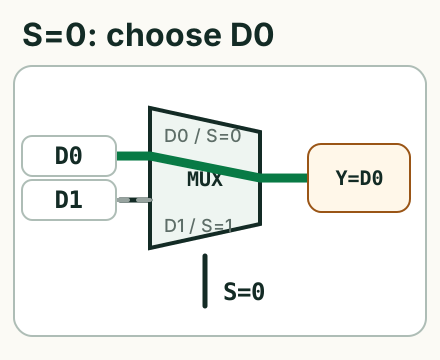
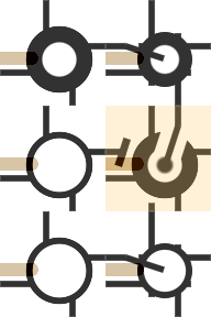
2×3 tiles1 MUX1 verified stateS=0 connects D0 to Y.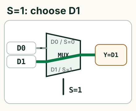
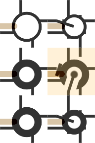
2×3 tiles1 MUX1 verified stateS=1 connects D1 to Y.The selector connects exactly one input path to the output. Composition turns that controlled connection into logic.
Four Sources Cover Every Behavior Of A
With A as the only live input, an output can equal 0, A, 1, or NOT A. The same MUX geometry creates all four, and a two-bit pointer names each source.
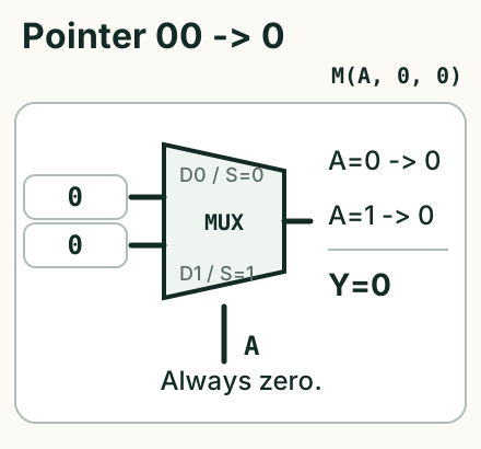
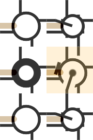
2×3 tiles1 MUX2 verified states00: tie both data inputs to zero. The result is always 0.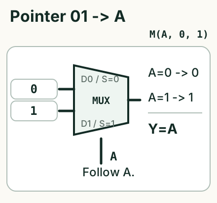
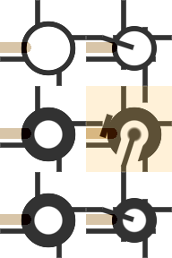
2×3 tiles1 MUX2 verified states01: choose between zero and one with A. The result follows A.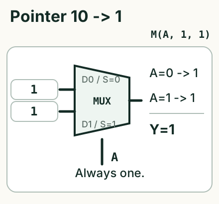
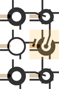
2×3 tiles1 MUX2 verified states10: tie both data inputs to one. The result is always 1.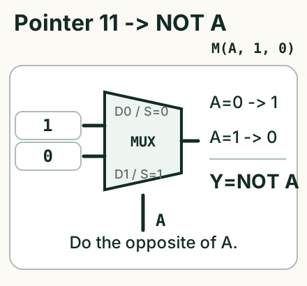
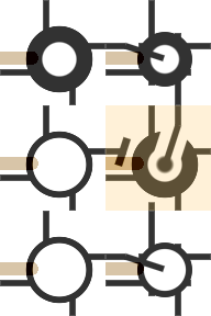
2×3 tiles1 MUX2 verified states11: choose the opposite constant with A. The result is NOT A.AND Emerges One Branch At A Time
Hold B constant and follow the output as A changes. Each value of B selects one of the four sources above.
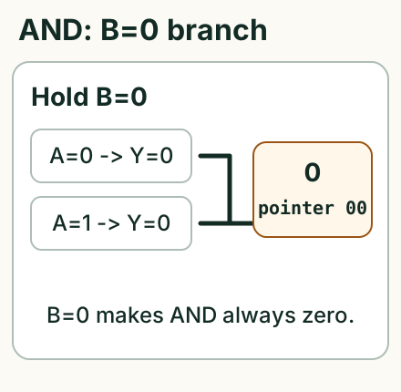
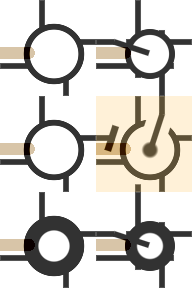
2×3 tiles1 MUX2 verified statesB=0, AND must be zero for both values of A. Choose source 0.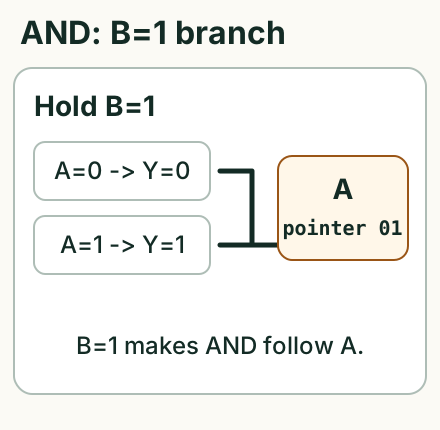
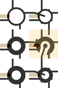
2×3 tiles1 MUX2 verified statesB=1, AND follows A. Choose source A.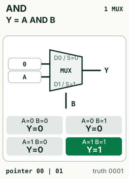
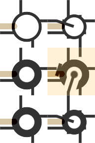
2×3 tiles1 MUX4 verified statesB=0 forces zero; B=1 passes A. Only A=1, B=1 produces one.AND = M(B, 0, A) pointer word 00|01 = 0001
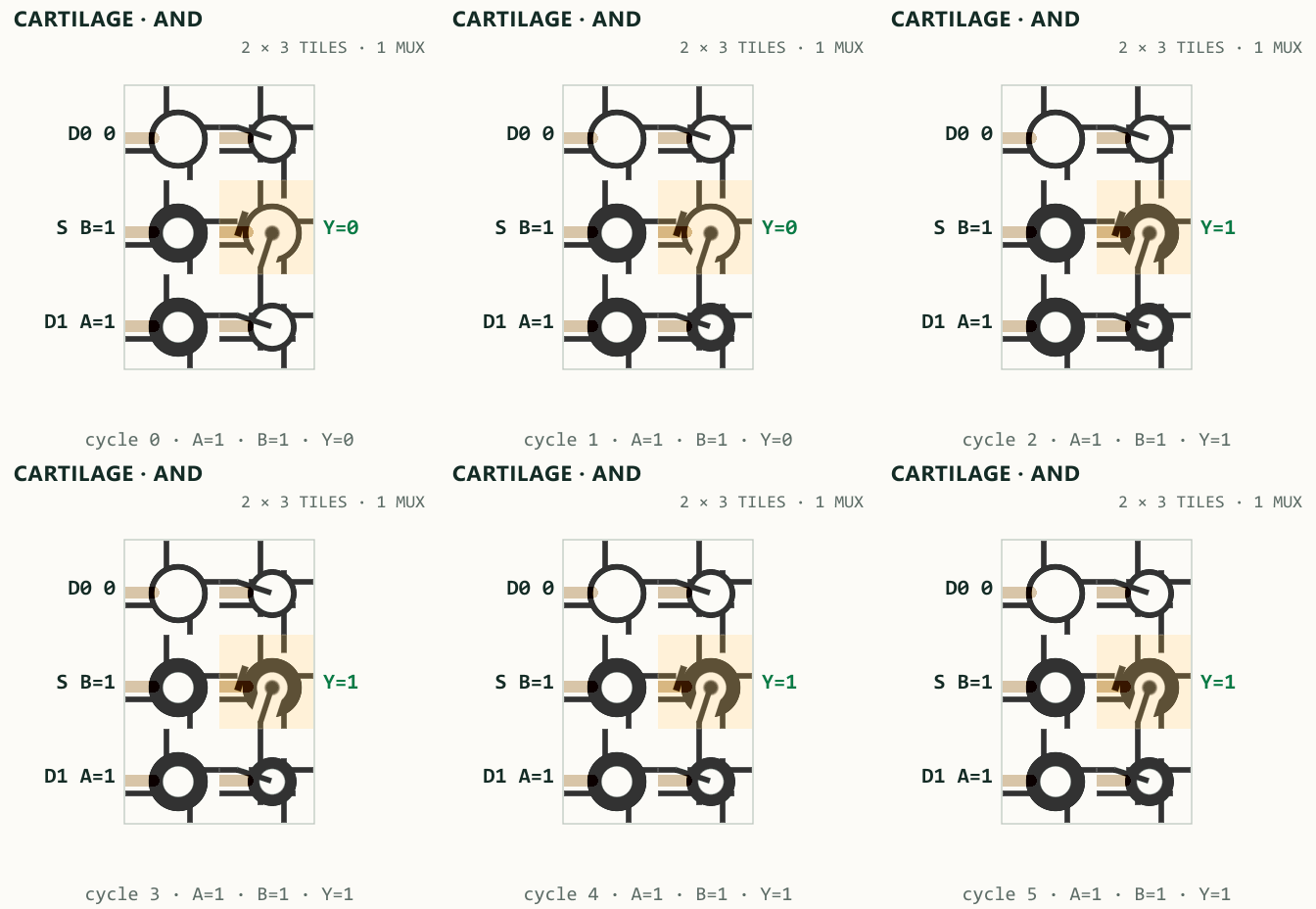
1 state enter the beige MUX tile: with A=1 and B=1, Y rises on cycle 2. A postprocess composites labels over unscaled renderer captures.The Construction Reaches All 16 Functions
Store the four truth bits directly
Store the outputs as C00, C10, C01, and C11. Two MUXes choose by A; a third chooses the correct column by B. Four freely chosen bits span all 16 two-input functions.


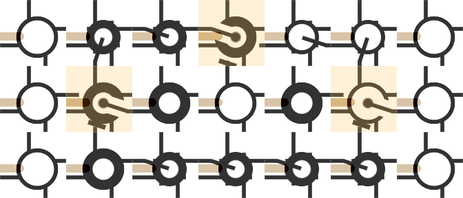
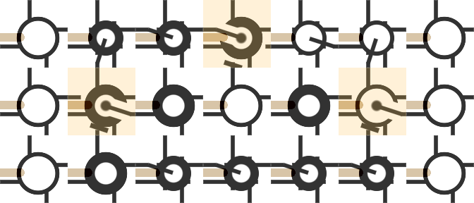
7×3 tiles3 MUXes64 verified states
Mobile: 7×3 tiles3 MUXes64 verified states
Store two source pointers
The 2020 construction uses another four-bit encoding. Each fixed-B column equals 0, A, 1, or NOT A, so two source addresses replace four direct truth bits.


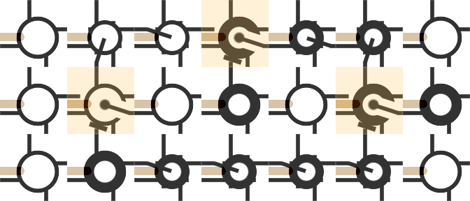
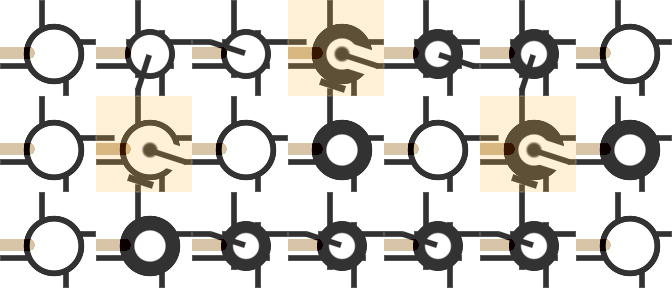
7×3 tiles3 MUXes64 verified states
Mobile: 7×3 tiles3 MUXes64 verified states
B column is one two-bit behavior of A, so each column needs only a two-bit source pointer.

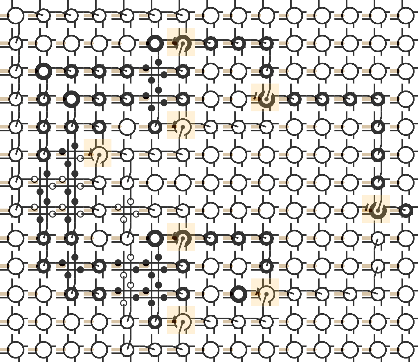
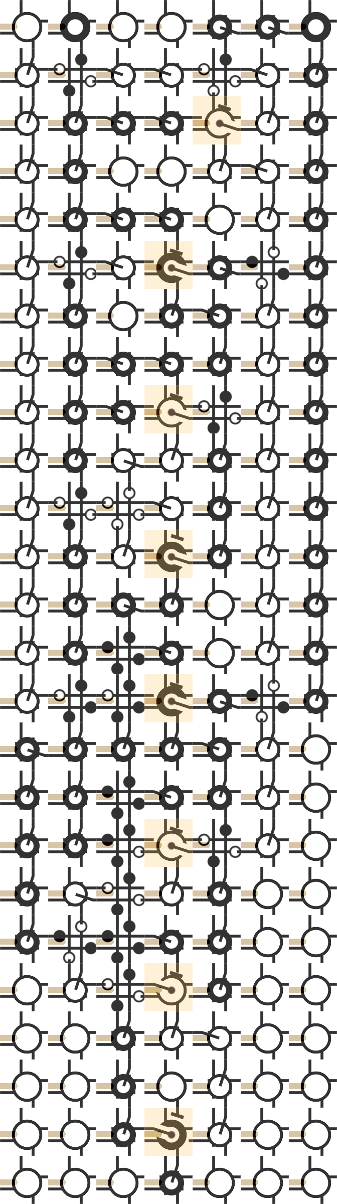
15×13 tiles8 MUXes64 verified states
Mobile: 7×25 tiles8 MUXes64 verified states
B=0 source. The low pair addresses the B=1 source.

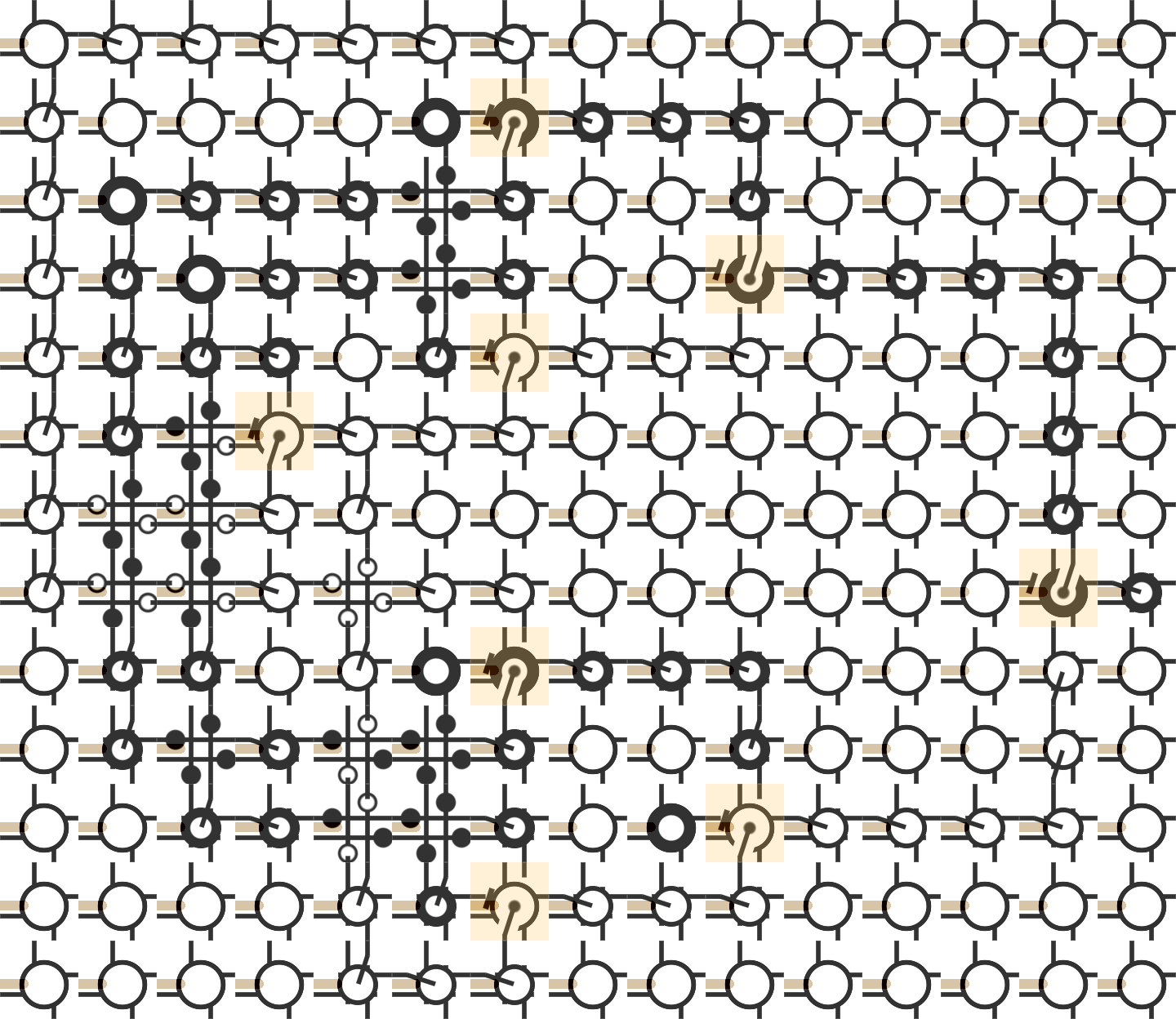
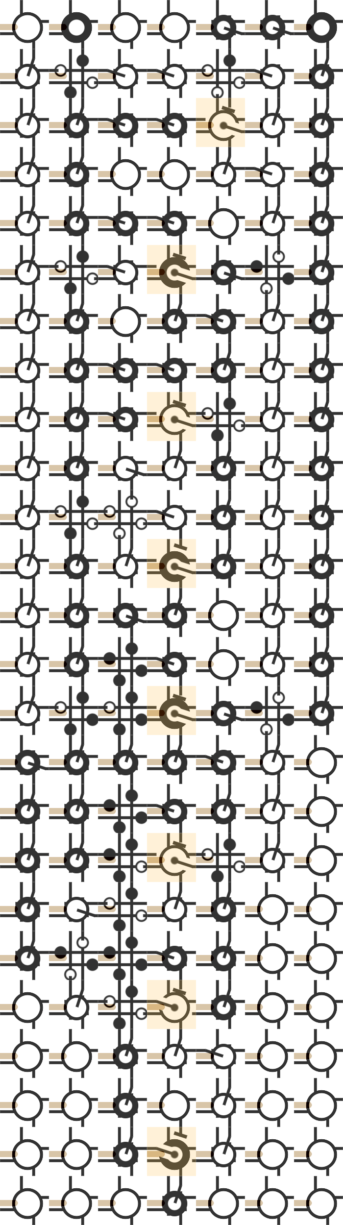
15×13 tiles8 MUXes64 verified states
Mobile: 7×25 tiles8 MUXes64 verified states
B chooses which addressed branch reaches Y.The two encodings record different things. A truth vector lists four outputs in the visible order A0B0, A0B1, A1B0, A1B1. The pointer word stores two source addresses in the order B=0 | B=1.
For example, XOR has truth vector 0110 but pointer word 01|11 = 0111.
Every Two-Input Function Becomes A Circuit
Each card shows minimal 2:1 MUX wiring, four visible truth outputs, and the pointer word. Constants and direct wires use zero MUXes. XOR, XNOR, NAND, and NOR use two; every other nontrivial function uses one.
When B=0, source 0 uses pointer 00
The high pointer pair is 00.
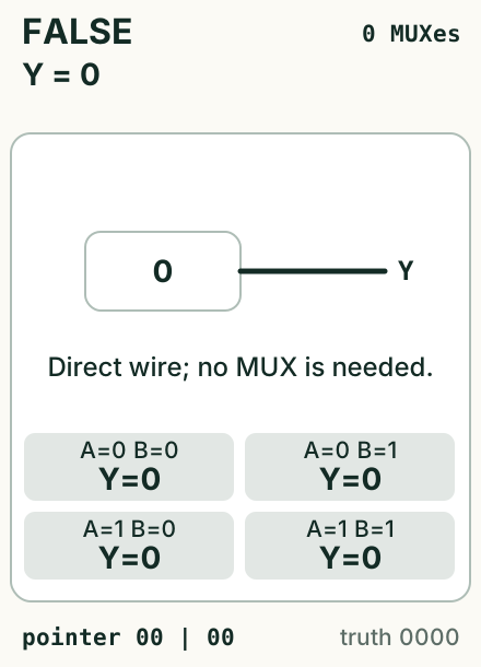

1×1 tiles0 MUXes4 verified statesY=0.
2×3 tiles1 MUX4 verified statesB=0 forces zero; B=1 passes A.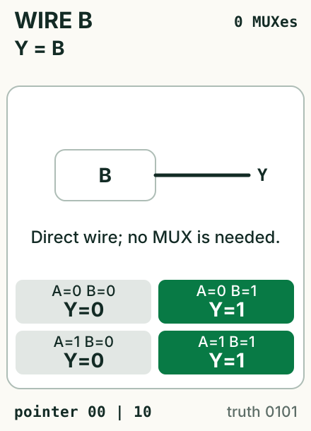

2×1 tiles0 MUXes4 verified statesY=B.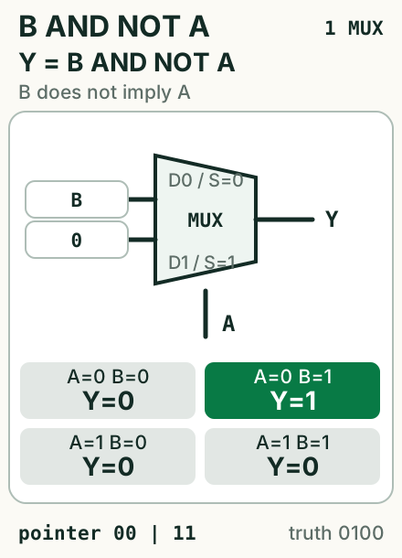
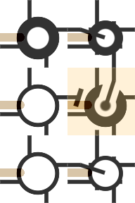
2×3 tiles1 MUX4 verified statesB AND NOT A, also B ↛ A: A=0 passes B; A=1 forces zero.When B=0, source A uses pointer 01
The high pointer pair is 01.
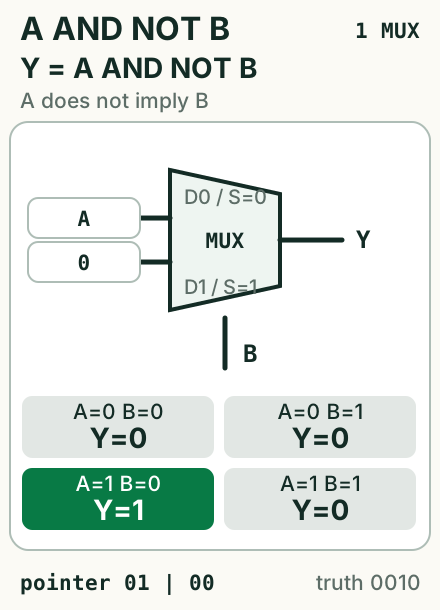
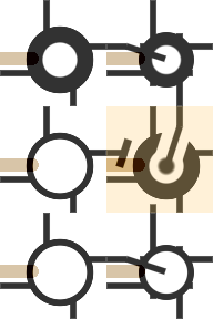
2×3 tiles1 MUX4 verified statesA AND NOT B, also A ↛ B: B=0 passes A; B=1 forces zero.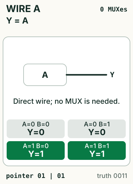

2×1 tiles0 MUXes4 verified statesY=A.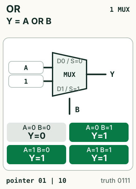
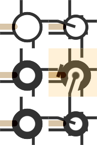
2×3 tiles1 MUX4 verified statesB=0 passes A; B=1 forces one.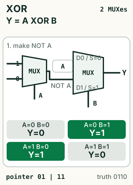
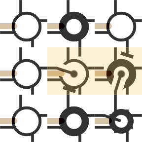
3×3 tiles2 MUXes4 verified statesNOT A; then let B=0 pass A and B=1 pass NOT A.When B=0, source 1 uses pointer 10
The high pointer pair is 10.
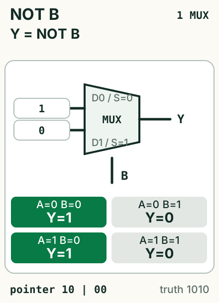
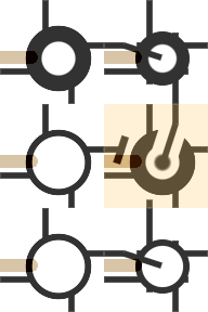
2×3 tiles1 MUX4 verified statesB chooses the opposite constant.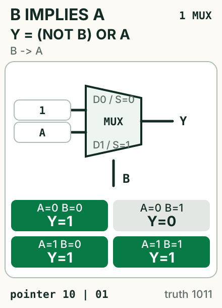
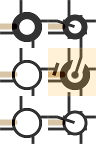
2×3 tiles1 MUX4 verified statesB → A: when B=0 the implication is true; when B=1 it follows A.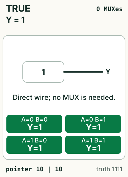

1×1 tiles0 MUXes4 verified statesY=1.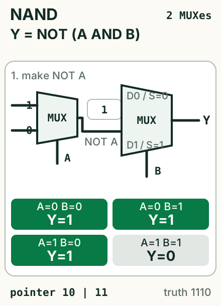
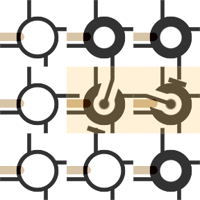
3×3 tiles2 MUXes4 verified statesB=0 forces one; B=1 passes NOT A.When B=0, source NOT A uses pointer 11
The high pointer pair is 11.
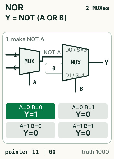
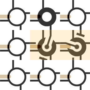
3×3 tiles2 MUXes4 verified statesB=0 passes NOT A; B=1 forces zero.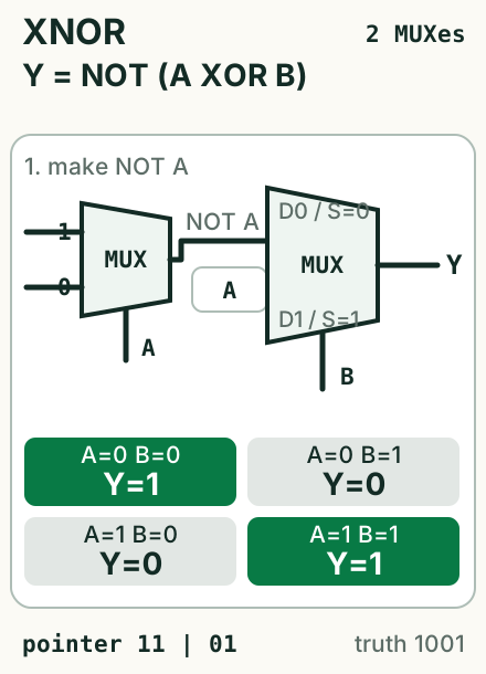
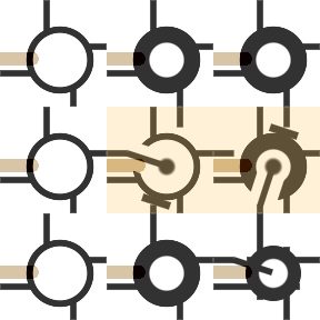
3×3 tiles2 MUXes4 verified statesB=0 passes NOT A; B=1 passes A.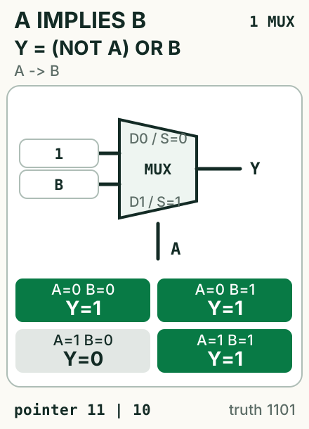
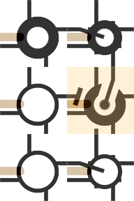
2×3 tiles1 MUX4 verified statesA → B: when A=0 the implication is true; when A=1 it follows B.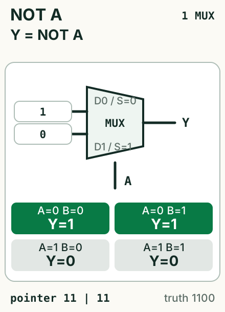
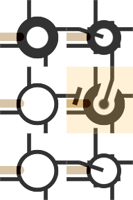
2×3 tiles1 MUX4 verified statesA chooses the opposite constant.Each New Input Adds One Selection Level
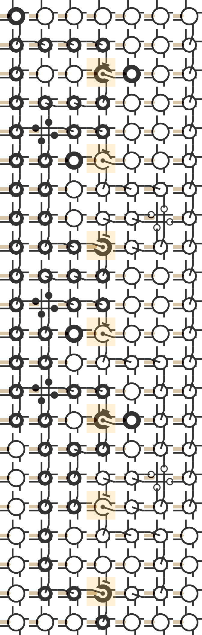
A third input selects between two functions from the catalog above. Repeat that decomposition until every branch reaches a constant, and nested MUXes express any Boolean function.


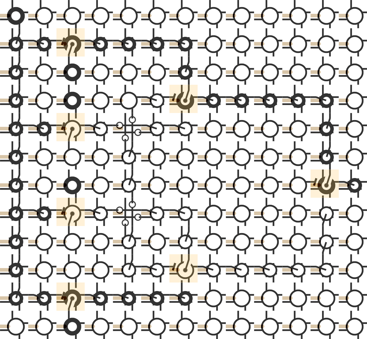
13×12 tiles7 MUXes8 verified states
Mobile: 7×22 tiles7 MUXes8 verified states
All 34 Circuits Run In Cartilage
Every one of the 34/34 teaching illustrations has a one-to-one Cartilage route, including five responsive mobile layouts. Shader readback covers 606 passing cases, and each labeled image includes a native-pixel capture.
Cartilage Core commit 48ff6e0 renders the routes through WebGL1 and GLSL. window.cartilage.loadState installs each state, window.cartilage.step advances it, and window.cartilage.readCell reads it back at 96 native pixels per tile.
Every 32×64 state begins with a reconfiguration-port root at (0,0). The checker reads all 2,048 cells before and after each truth-table case and rejects parent-pointer search or any changed parent field. Native zoom and three host-injected boundary cells initialize the capture copy; the GLSL transition and renderer remain identical.
The run executes already routed application circuits. The serial installer supplies the complementary path from configuration stream to placed circuit.
Open the capture, routing, truth-check, and SHA-256 manifest.
The 2020 Logisim Circuits Started The Construction
Five original Logisim circuits precede the paired teaching views and sit outside the 34/34 generated-illustration count.
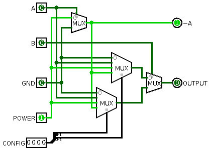
B selects the final branch.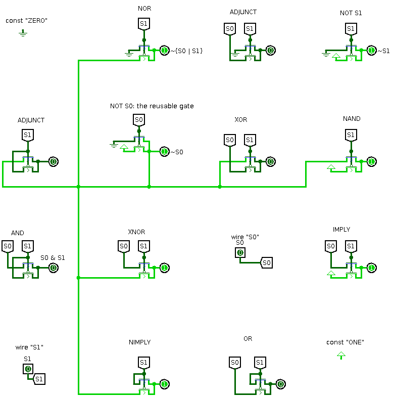
S0=0, S1=0.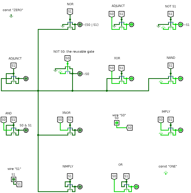
S0=1, S1=0.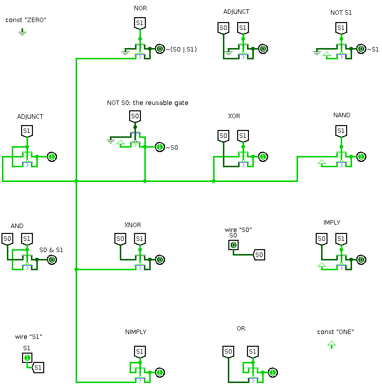
S0=0, S1=1.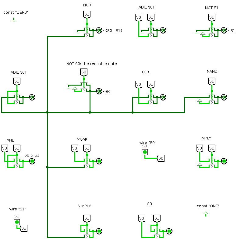
S0=1, S1=1.The MUX-algebra construction dates to March 22, 2020; the transistor-level LUT2 follow-up dates to March 23. This edition standardizes variables as A and B and aligns both implication labels with their truth tables.
The Logisim drawings show functional selector networks. A transistor implementation chooses its count through MUX topology, complemented-selector generation, source sharing, loading, and output drive. The original "16 CMOS transistor" LUT2 count corresponds to one such arrangement.
Exact executable definition
function muxAlgebra(a, b, config) {
    const sources = [0, a, 1, Number(!a)];
    const pointer = b ? (config & 0b11) : (config >> 2);
    return sources[pointer];
}

muxAlgebra(1, 1, 0b0001); // AND  -> 1
muxAlgebra(1, 1, 0b0111); // XOR  -> 0
From One Selector To A Reconfigurable Computer
The Logisim-to-LUT learning path grows this rule from LUT1 through LUT6 and connects it to Lattice and AMD/Xilinx FPGA primitives. The physical MUX tiles turn selectors, constants, routes, intersections, and orientation into objects you can arrange by hand. Boolean Algebra Is All That Is Required carries the same construction into storage, configuration transport, ownership, and an extensible fabric.