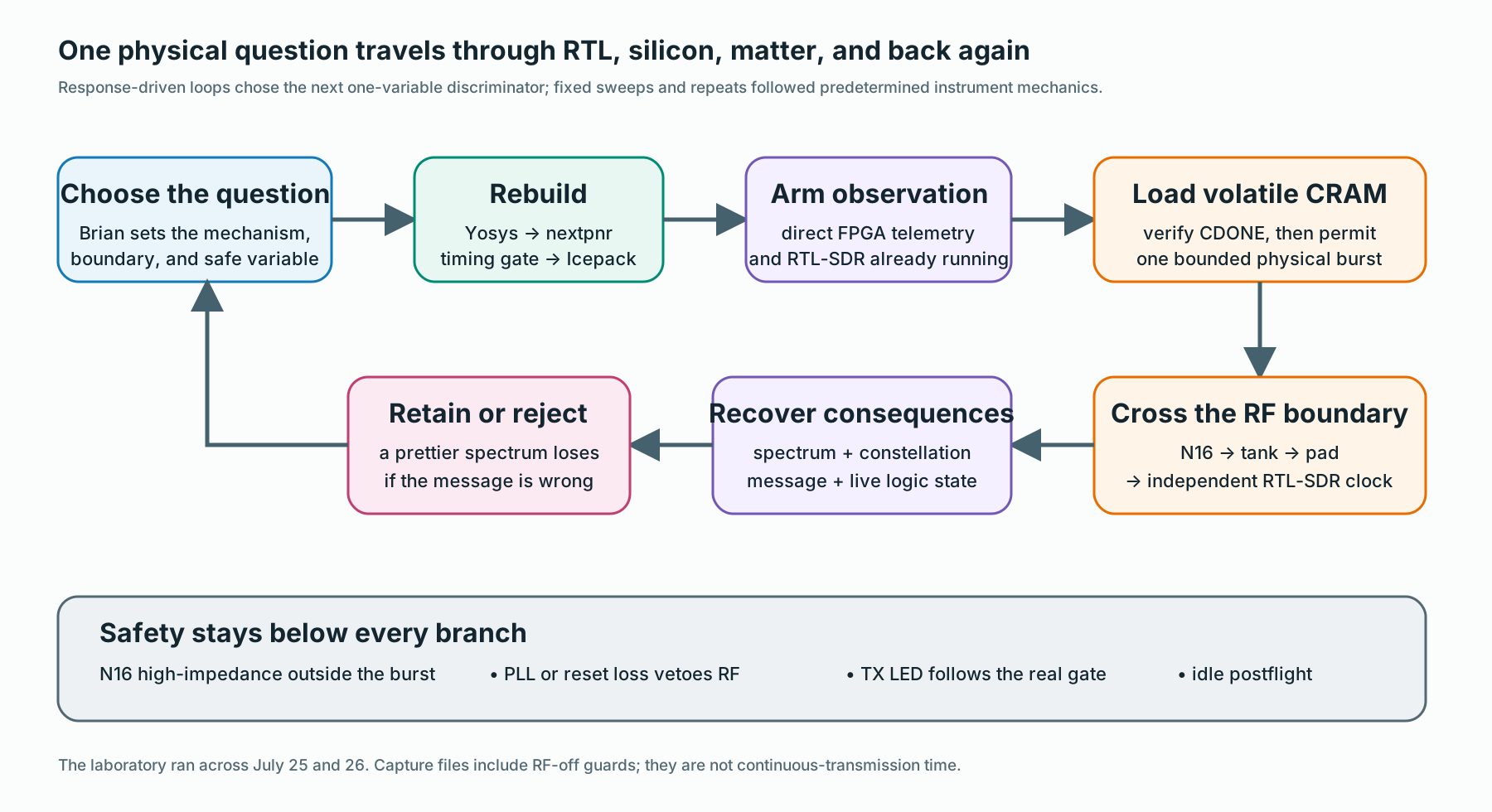
Human Engineering Judgment Drove Every Automated Pass
Human engineering judgment set the architecture, physical connections, 222–225 MHz working boundary, safety rules, question for each experiment, and single variable allowed to change. Those choices determine what an RF result means; no directory of captures can reconstruct them later.
Orchestration handled the repeatable mechanics. It edited the nominated parameter, ran Yosys and nextpnr, checked timing, started direct telemetry, waited for the RTL-SDR ready handshake, loaded volatile CRAM, verified CDONE, commanded one finite burst, captured the off/on/off interval, recovered the packet or audio, and returned the output to its idle state. Predetermined instrument routines handled ordinary sweep segmentation, gain sweeps, and unchanged repeats.
The physical response selected each next setting in three branches: Run 14 through Run 17, Run 33 through Run 36, and the later PLL-delay branch. Everywhere else, automation executed a previously defined experiment. This division kept physical authority narrow and let the receiver guide the next build quickly.
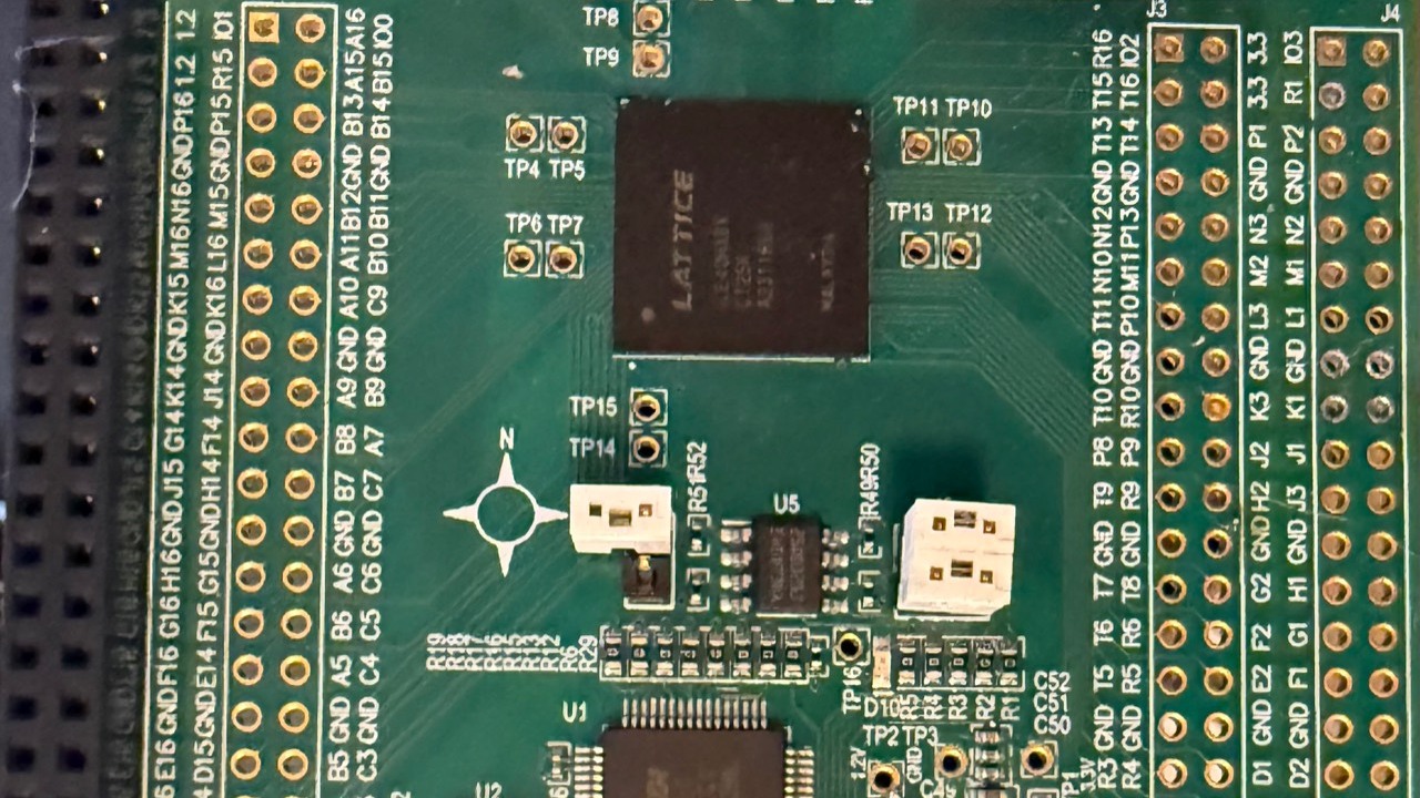
One Question Crossed the Whole Machine
- Define one physical question. Name the measurement, allowed band, safety condition, and one variable to change.
- Build the exact digital change. Yosys and nextpnr synthesize, place, and route it. Any timing or topology failure stops the branch before the board sees a new image.
- Start the observers first. Direct FPGA telemetry starts, then the RTL-SDR arms and confirms that samples already flow.
- Load volatile CRAM. The orchestration programs the image through FTDI/D2XX, checks CDONE, and leaves persistent configuration memory untouched.
- Capture one bounded event. The receiver starts before the burst, so one capture holds RF-off guard time, the burst, and the return to quiet.
- Join both sides of the physical path. Direct telemetry identifies what the FPGA applies; independent IQ samples show what crosses N16, the tank, the pad, cable, tuner, and receiver.
- Recover the information. Packet length, CRC, symbols, bits, EVM, and timing decide whether a change still carries the message.
- Keep, reject, or restore. A successful discriminator starts the next single change. A failure reloads the last accepted image.
- Confirm the idle state. Postflight telemetry must show N16 high-impedance and the transmit LED off before the loop advances.
From 11:13 PDT on July 25 through 20:43 PDT on July 26, the campaign spanned 33 hours, 30 minutes. Inside that interval, the lab made 171 RTL-SDR acquisitions and 87 configured NanoVNA sweeps, saved 133 raw IQ captures, and performed 70 volatile FPGA loads across 42 digital configurations. These figures count bounded instrument and programming operations; they neither count equivalent experiments nor describe continuous RF transmission. Every receiver acquisition includes its RF-off guard intervals.
July 25: The Bench Began Answering Clean Questions
The first day removed ambiguity from the physical path. The work corrected the antenna, coupler, LNA, attenuation, and 50-ohm terminations; separated passive NanoVNA work from active SDR work; and retired an early H8 configuration when its tuner failed to lock as intended. The lab powered down the NanoVNA before transmitter captures.
- 11:13 PDT
- The session began with the physical connections and safe operating boundary, before any RF optimization target.
- 12:22–13:44
- Receiver and fixture baselines exposed the topology mistakes and fixed the antenna, coupler, LNA, attenuator, and termination arrangement.
- 14:59–15:37
- Wide views, gain checks, finite on/off behavior, and the high-impedance idle state established the context for later narrow measurements.
- 16:06–17:58
- Q-sign reversal, tone, amplitude, sawtooth, and phase-ramp experiments made the one-pin boundary answer elementary causal questions.
- 18:49–20:22
- Two-axis audio and system-identification experiments tested whether richer structure survived the physical path.
- 20:42 onward
- The loop moved into QPSK and FM. The first retained volatile programming operation followed at 00:36 PDT on July 26.
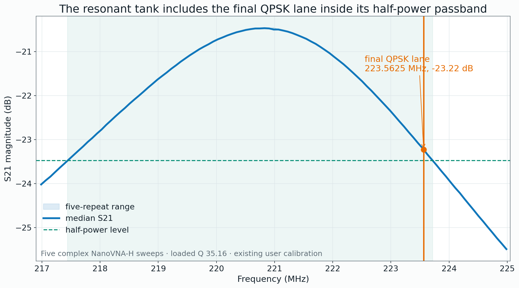
Five complex sweeps of the passive tank put the median S21 maximum at 220.782991 MHz. The half-power crossings landed at 217.439055 and 223.718667 MHz, producing a 6.280417 MHz loaded bandwidth and a loaded Q of 35.1575. That measured passband later placed the final 223.5625 MHz QPSK lane only 156.167 kHz inside the upper half-power crossing.
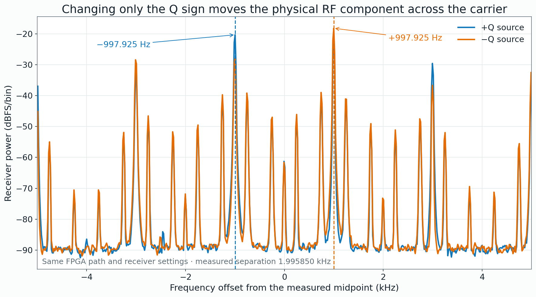
Changing only the sign of Q moved the received component from 997.925 Hz below the measured midpoint to 997.925 Hz above it, a 1.995850 kHz crossing. The digital quadrature choice controlled which side of the physical carrier received energy and gave the later packet work a deliberate directional control.
July 26: Receiver Results Directed the Next Build
At 02:38 PDT, Run 14 recovered all 1,800 transmitted bits and passed CRC while giving 7.661408 dB of separation from the unwanted comparison window. The physical response called for a half-sized frequency warp rather than a full correction. At 03:02, Run 17 preserved the exact 1,800-bit recovery and raised that separation to 10.435617 dB, an improvement of 2.774209 dB. It also reduced separation from the central LO by 1.011560 dB. One event revealed both the improvement and its cost.
The sharper sequence began at 04:40. Run 33 passed its packet check with 8.865934 dB of raw separation between opposite windows. The pattern located Q on the wrong adjacent phase at the first IF mixer. In that RTL snapshot, the Johnson counter served specifically as the quadrature IF oscillator; the next build changed only the Q input tap from phase 1 to phase 0.
Run 35 at 05:09 raised the separation to 20.583482 dB, an 11.717548 dB improvement, while the frame length and CRC still passed. Run 36 at 05:23 looked even better in the spectral window: 23.744552 dB. Its recovered message told the opposite story: it returned the wrong length, failed CRC, reached 96.152% decision-referenced EVM, and reached 93.617 degrees of angular jitter. Three minutes later, the orchestration restored Run 35.
That reversal captures why I built the loop. A spectrum analyzer can reward a change that destroys the communication system. Recovered information kept the nicest-looking failure out of the next design.
One PLL Tap Improved the Image and Worsened the Carrier
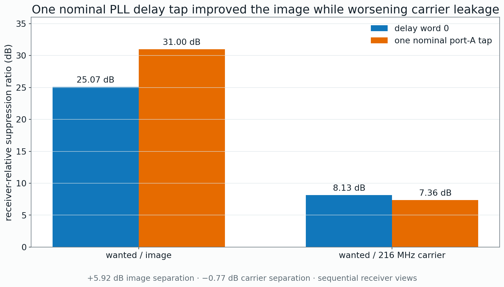
Later that afternoon, a sideband swap would have moved the predicted dominant output outside the 222–225 MHz boundary. That boundary stopped the branch before transmission. The next pass added one nominal delay tap on PLL port A and held the rest of the transmitter constant.
The lab acquired Physical 24 through Physical 26 from 16:09 to 16:21 PDT and separated three questions into fixed receiver views. In the 25 kHz integration windows used for the main comparison, wanted-to-image separation moved from 24.7769 to 30.0123 dB. Wanted-to-carrier separation moved the other way, from 8.1091 to 7.3466 dB. The tap traded carrier separation for image separation, so the design needed both numbers.
Physical 27 Returned 8,592 Checked Bits With No Observed Errors
The accepted Physical 27 image closed at 16:48 PDT. It used 2,127 of 7,680 logic cells, one PLL, no block RAM, three global networks, and seven package I/O sites. Its routed maxima reached 84.78, 115.81, 108.67, and 244.20 MHz for the four declared domains, including the 216.03 MHz RF-phase domain.
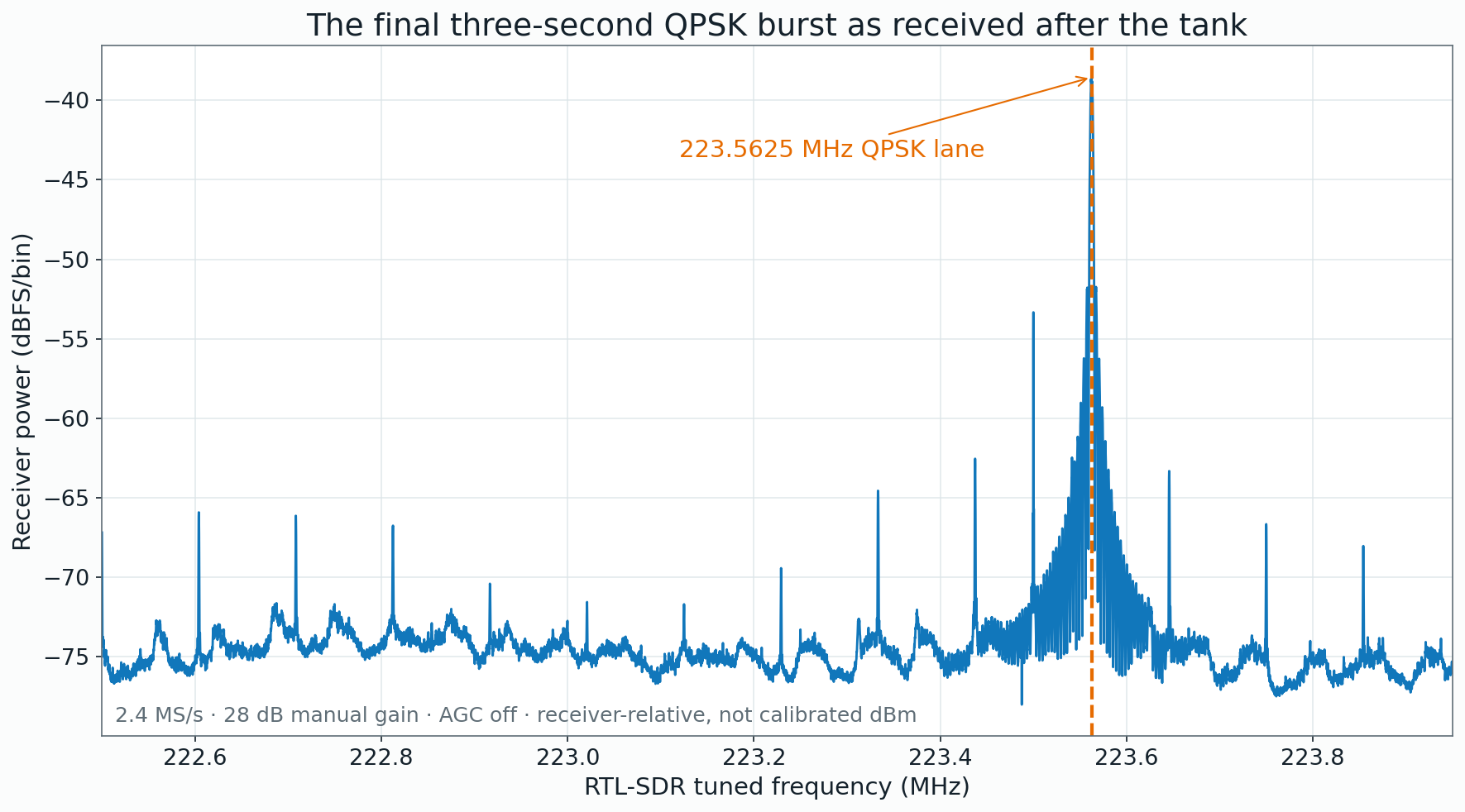
At 16:56, the orchestration started telemetry, waited for the SDR, programmed volatile CRAM, verified CDONE, issued one three-second burst, and left the receiver running long enough to observe quiet on both sides. Direct telemetry associated the actual PRBS16 QPSK state with the independent IQ stream rather than inferring the transmitted state from the receiver alone.
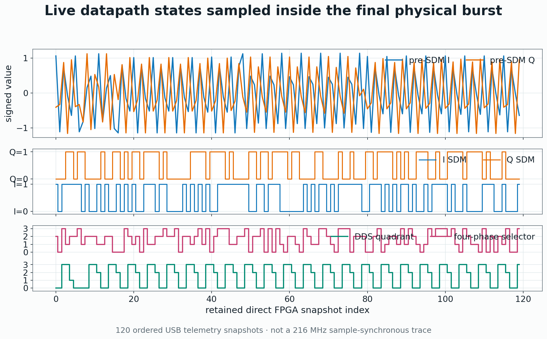
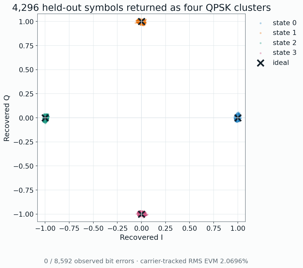
The QPSK source ran at 3,295.8984375 symbols per second, or 6,591.796875 gross bits per second. After acquisition, 4,296 directly observed held-out symbols produced 8,592 checked bits with no observed errors. Carrier-tracked RMS EVM reached 2.0696% and normalized correlation reached 0.999584. The receiver used known symbols only for initial acquisition; phase tracking over the held-out region did not use the transmitted bit decisions.
The nominal held-out span contained 5,623 epochs. Direct telemetry reached 4,296 of them; the other 1,327 remained holes. Across the complete run, direct telemetry covered 7,555 epochs and left 2,332 holes. No interpolation turned those holes into successes. After the burst, 22,528 idle telemetry frames reported no burst request, no RF-enable state, and no transmit LED activity.
Physical 28 Measured the Conjugate Image With One Receiver Change
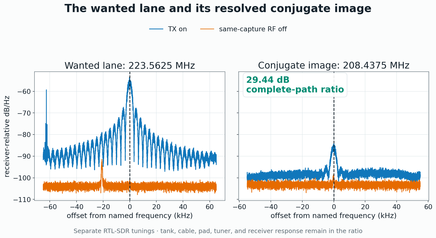
At 17:50 PDT, Physical 28 changed one thing outside the FPGA: the RTL-SDR tuned from 223.4875 MHz to 208.3625 MHz to look at the conjugate image. The FPGA image, transmitter profile, SDR gain, sample rate, cable path, and receiver stayed otherwise unchanged.
The sequential complete-path comparison produced 29.4439 dB of wanted-to-image separation in fixed 25 kHz windows. This complete-path value combines the tank, pad, cable, tuner, RTL-SDR frequency response, and intrinsic Weaver contribution in one physical result.
Finite Bursts and the Chamber Controlled the RF Session
The RF chamber set the physical safety boundary, and the transmitter produced finite one-shot bursts rather than continuous RF. Physical 27 and Physical 28 both ended with telemetry showing N16 high-impedance and the transmit LED off. The orchestration required that postflight condition before starting another branch.
This session left no chamber photograph or exterior calibrated field-strength sweep. Accordingly, this work makes no claim of measured containment, outdoor legality, or regulatory compliance. The next chamber pass can record distance, antenna factor, orientation, detector and bandwidth settings, ambient baseline, and uncertainty together.
The Same Loop Opens a Richer Measurement Plane
The next measurement plane can add a complete tank schematic and measured BOM, fixture geometry, loading, cables, and named reference planes. A raw TDS3034C waveform at the intended RF output plane can connect the exact FPGA image, carrier setting, load, and scope configuration. Traceable amplitude calibration and conducted power with uncertainty can supply absolute quantities where relative receiver units cannot.
A common trigger or clock between FPGA telemetry and RF acquisition can support repeated bursts across supply and temperature, drift tracking, and BER versus controlled condition. A simultaneous target/image receiver can remove the sequential frequency-response ambiguity in Physical 28. Wider calibrated chamber sweeps and final-profile harmonic work need instruments and fixtures chosen for those frequency ranges.
With that measurement plane, the same loop can control multiple active lanes, choose discriminators that separate image, carrier, flatness, timing, and message recovery, and expose safe predetermined experiments through a browser. Every digital idea still crosses the physical machine and returns as an intelligible consequence before it earns the next experiment.
Market opportunity: AI-controlled laboratories need a vendor-neutral benchmark that tests whether an agent can complete an absolute-power measurement after recognizing uncalibrated receiver units. This campaign exposed exactly that need and led to a proposal for a vendor-neutral physical benchmark for engineering agents.