Cartilage Visual Language
June 26, 2026

Cartilage renders are circuit diagrams drawn from a small cell-role alphabet. The visible marks are not arbitrary icons: they come from the body role stored in each cell, the cell orientation, and the local wires crossing the four sides of the tile.

The compact decoder is 32 roles: four special roles, four wire orientations, and six MUX modes in four orientations each.

The Render Key

Cartilage fabric visual-language key showing port, cross, constants, wires, and MUX body types
A 13x13 Cartilage fabric render showing the body-role vocabulary: port, cross, constants, wire orientations, and MUX roles.

How The 32 Codes Are Packed

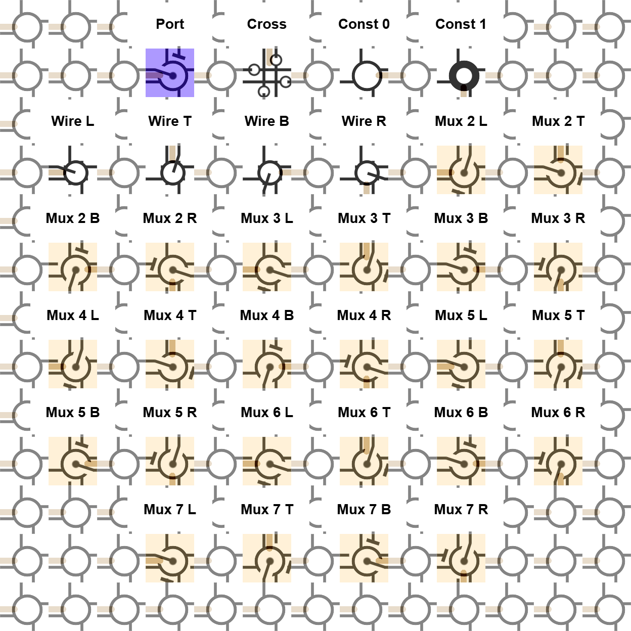
The renderer stores the visible role as two fields: orientation is two bits, and mode is three bits. The natural body-type code is orientation + 4 * mode, giving codes 0 through 31.

Mode 0 is special: its four orientations mean port, cross, constant zero, and constant one. Mode 1 is a wire. Modes 2 through 7 are the six MUX behaviors, each rotated into four render orientations.

The suffixes L, T, B, and R name the rendered orientation. Read them as local tile orientation labels, not as a global coordinate system.

Cell Role Codes

Code
Role
Purpose
00
Port
Local reconfiguration port. It is the tile role through which a parent-owned stream can enter a bounded child region and replace that region's body roles.
01
Cross
Intersection role. It lets routes cross in the drawn fabric and keeps directional state for crossing paths without turning the tile into a MUX.
02
Const 0
Fixed zero source. This is the ground role used when a local circuit needs a constant low value.
03
Const 1
Fixed one source. This is the power role used when a local circuit needs a constant high value.
04
Wire L
One-input pass-through in left orientation. Wire roles move one local signal through the cell without adding selection logic.
05
Wire T
One-input pass-through in top orientation. Same wire behavior as Wire L, rotated in the rendered tile.
06
Wire B
One-input pass-through in bottom orientation. It is used for a routed signal segment through the local fabric.
07
Wire R
One-input pass-through in right orientation. Same wire role, rotated to the right-facing drawing.
08
Mux 2 L
Mode 2 MUX in left orientation. Canonical local rule: selector chooses B when high, otherwise R.
09
Mux 2 T
Mode 2 MUX in top orientation. Same B/R selection behavior, rotated in the tile drawing.
10
Mux 2 B
Mode 2 MUX in bottom orientation. The mode defines the two data choices; the suffix defines the rendered rotation.
11
Mux 2 R
Mode 2 MUX in right orientation. This is the right-rotated form of the same selector/data pattern.
12
Mux 3 L
Mode 3 MUX in left orientation. Canonical local rule: selector chooses R when high, otherwise B.
13
Mux 3 T
Mode 3 MUX in top orientation. Same R/B selection behavior, rotated in the tile drawing.
14
Mux 3 B
Mode 3 MUX in bottom orientation. The render shows which rotated form is installed in that cell.
15
Mux 3 R
Mode 3 MUX in right orientation. Same logic role as mode 3, rotated to the right-facing drawing.
16
Mux 4 L
Mode 4 MUX in left orientation. Canonical local rule: selector chooses T when high, otherwise R.
17
Mux 4 T
Mode 4 MUX in top orientation. Same T/R selection behavior, rotated in the tile drawing.
18
Mux 4 B
Mode 4 MUX in bottom orientation. It is another rotated installation of mode 4 selection logic.
19
Mux 4 R
Mode 4 MUX in right orientation. Same MUX function, right-oriented in the render.
20
Mux 5 L
Mode 5 MUX in left orientation. Canonical local rule: selector chooses R when high, otherwise T.
21
Mux 5 T
Mode 5 MUX in top orientation. Same R/T selection behavior, rotated in the tile drawing.
22
Mux 5 B
Mode 5 MUX in bottom orientation. The role is mode 5; the suffix is the visual rotation.
23
Mux 5 R
Mode 5 MUX in right orientation. Same selection role, right-rotated in the fabric drawing.
24
Mux 6 L
Mode 6 MUX in left orientation. Canonical local rule: selector chooses T when high, otherwise B.
25
Mux 6 T
Mode 6 MUX in top orientation. Same T/B selection behavior, rotated in the tile drawing.
26
Mux 6 B
Mode 6 MUX in bottom orientation. This is the bottom-oriented installation of mode 6.
27
Mux 6 R
Mode 6 MUX in right orientation. Same selector/data role, right-rotated in the render.
28
Mux 7 L
Mode 7 MUX in left orientation. Canonical local rule: selector chooses B when high, otherwise T.
29
Mux 7 T
Mode 7 MUX in top orientation. Same B/T selection behavior, rotated in the tile drawing.
30
Mux 7 B
Mode 7 MUX in bottom orientation. The rendered body is the bottom-oriented form of mode 7.
31
Mux 7 R
Mode 7 MUX in right orientation. This is the right-rotated form of the final MUX mode.

How To Read The Drawing

Black marks are asserted local state or output values in the render. White rings are cell/port positions. Tan overlays mark MUX-like structure and visible value flow. Purple marks the reconfiguration-port role. The labels in the image are explanatory labels drawn over the fabric; the fabric itself is still the 32-code cell-role alphabet above.

This is the low-level visual vocabulary behind the larger Cartilage articles. A reconfiguration run is easier to inspect once the reader knows which marks mean constants, wires, crosses, MUXes, and ports.