The Rendered Artifact
The Circuit
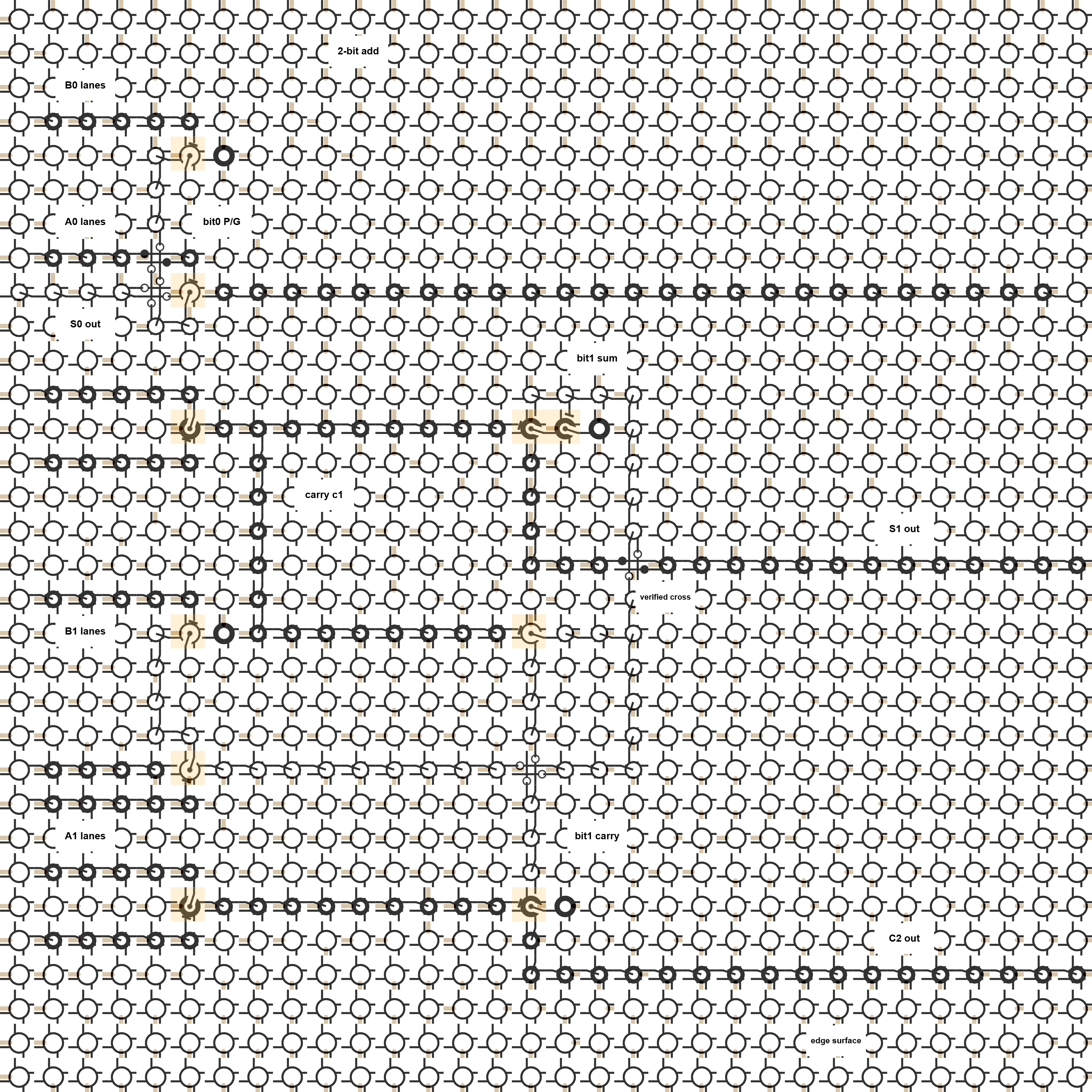
The adder consumes all 16 pairs of two-bit inputs and exposes the three-bit result:
{C2, S1, S0} = A[1:0] + B[1:0]The generated QFG places the primitive Cartilage cells directly. The crossbars visible in the screenshot are intentional generated cells, not accidental overlay intersections.
The Proof Run
The browser/GLSL lockstep run streamed the QFG frames through the fabric and checked the result at frame boundaries:
207 explicit seed cells
16 parsed QFG frame declarations
3072 lockstep fabric updates
96 browser expectations checked
96 browser expectations passed
The correctness claim comes from the verification report and QFG source, not from simply looking at the picture.
Output Surface
The result bits are routed to ordinary edge-visible readout lanes:
S0 exits on the left edge at row 8
S1 exits on the right edge at row 16
C2 exits on the right edge at row 28
The final checked frame is a=3, b=3, so the expected result is binary 110. The final edge readout has active right-edge lanes 16 and 28, matching S1=1 and C2=1; S0=0 is inactive.
Artifacts
The source netlist is available as browser-static-ripple2-adder-edge.qfg. The full verification report is available as verification-report.md.
The screenshot is a visualization of those artifacts. It is useful because it lets a reader inspect the placed fabric, but the proof comes from the generated QFG and the expectation checks.
What This Replaces
The previous full-adder islands, PC-stepper islands, and mux-lanes pages are now treated as withdrawn artifacts. The first two are visual placement sketches without edge-surface proof. The mux-lanes page is a useful proof/debug fixture, but not the requested clean visitor-facing schematic.
This ripple2 adder is the current public replacement: generated source, inspectable render, edge-visible result lanes, and a passing browser expectation run.