Build Every Route Through A Physical Stack
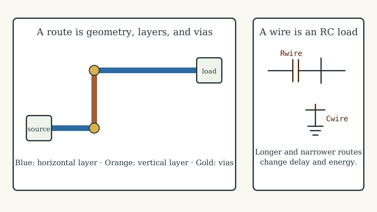
Integrated circuits use multiple conducting layers separated by dielectric. Design rules define widths, spacings, enclosures, pitches, allowed directions, and via structures. A route follows one layer, changes layers through a via, and reaches a pin shape on a cell or macro.
Designers assign preferred directions and distinct roles to each layer, reserving one range for signals and another for clocks when the flow requires it. OpenROAD’s global-routing documentation exposes separate signal and clock layer ranges plus layer-by-layer capacity adjustments.
Turn Resistance And Capacitance Into Spatial Delay
A metal segment contributes resistance along its length and capacitance to neighboring conductors and the substrate. Vias add resistance and geometry, while the driver charges or discharges the combined wire and input capacitance.
OpenROAD’s parasitics-estimation reference lets a flow set resistance and capacitance by routing layer, distinguish clock and signal wire models, and estimate parasitics from placement or global routing. “Net A connects to B” therefore becomes “this route through these layers has an estimated physical cost.”
Make Finite Routing Capacity Part Of Placement
Each layer contains a finite number of legal tracks. Pins, macros, power structures, blockages, and routed nets consume access and capacity. Dense demand makes the router detour, change layers, add vias, or report that no legal solution remains.
Congestion can turn the shortest abstract connection into a long physical route. Placement, floorplanning, hierarchy, and high-fanout structure therefore shape timing before any gate delay changes.
Use Every Cartilage Side-Metal As A Local Route
The preserved cartilage3 substrate gives each square cell three incoming and three outgoing directional connections on each of four sides—24 edge “metals” per cell, excluding power. Sixteen belong to the Sinew reconfiguration overlay; eight carry application or intersection state.
Local neighbor reads and texture ping-pong move these values through the WebGL fabric, so path length and region shape directly determine simulated update latency. Physical implementation adds resistance, capacitance, electromigration, crosstalk, and foundry-rule analysis to that spatial topology.
The nested-instantiation mechanism shows local configuration data and ownership using those neighboring relationships while the canonical shader keeps its original execution path.
Keep The Word “Metal” Attached To Physical Cost
A value occupies a path, crosses a boundary, consumes local connection capacity, and arrives after propagation. The word “metal” keeps that spatial and physical cost inside the architecture.
Physical Cartilage implementation maps logical side-metals onto concrete FPGA routing or IC layers, extracts or estimates delay, satisfies design rules, and closes timing. That mapping turns logical adjacency into a characterized physical route.
Use Routes To Make Ownership Concrete
A nested component occupies a bounded region. Its ports consume routes, its parent reaches those routes, and its independent reconfiguration uses a configuration surface distinct from ordinary application composition.
The next chapter carries that physical structure into nested source definitions, composed circuitry, and parent-owned daughter regions.