A Compute Graph Needed Multiplication In Stream Form
Brian invented the circuit on July 26, 2025, when a standard Verilog * slowed timing closure and scarce hard multiplier blocks constrained the intended compute graph. The graph needed multiplication that moved like its other signals: one bit per link, one clock per step, every word touching the next.
The first complete form was an inspectable 8-by-8 Logisim circuit. It accepts positive operands LSB-first and produces the low eight product bits. Its balanced serial reduction tree creates a fixed three-clock latency while preserving one output bit on every clock after fill.
That eight-bit circuit established the architecture. The finished FPGA work carries the same arithmetic structure to 64-bit operands, adds bounded registered fanout and full retiming, and keeps the defining property intact: width changes the amount of spatially repeated machinery, never the continuous word cadence.
The Original Circuit Remains Directly Inspectable
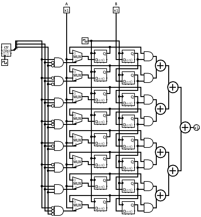
serial_july_2025.circ opens in Logisim 2.7.1. The project contains reusable var, add, and mul circuits plus inspection harnesses. mul.png renders the complete multiplier, and add.png renders the serial adder.
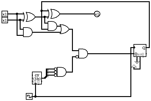
varserializes each value into an LSB-first one-bit stream.addevaluates a full-adder bit and retains carry as local clocked state.mulgates delayed operand streams into partial-product lanes and reduces them through a balanced tree.dbg,main, andmain2expose the schedule for direct inspection.
The circuit file SHA-256 is 3317a9e721381e927b2fd307e1fd4b2139ab05036ef2cbea2129e36f2a74c597. The download package carries that exact circuit beside its FPGA descendant.
Partial Products Move Through Time Instead Of A Wide Matrix
For each multiplier bit, a lane retains the corresponding A bit and gates it with the appropriately delayed B stream. The resulting one-bit partial-product streams enter pairs of serial adders. Each adder produces one sum bit per clock and keeps only its carry recurrence locally.
Six reduction levels combine 64 lanes into one low-product stream. A new A/B bit pair enters while older products occupy every level of the tree. Once filled, the tree behaves like a continuously moving graph, not a transaction that starts, works, drains, and restarts.
This is the practical meaning of bubbles-free: the architecture has latency, but no inter-word vacancy. At 216 MHz and 64 clocks per operand, its rate is exact:
216,000,000 clocks/s / 64 clocks/product = 3,375,000 products/s
The FPGA Translation Preserves The Circuit's Arithmetic
The 64-bit SystemVerilog was reconstructed from the published circuit rather than treating generated companion Verilog as the authority. It preserves 64 A holds, a 64-stage B delay, 64 partial-product lanes, and the 63 serial adders of the balanced reduction tree.
The literal eight-bit translation exposed one phase detail worth getting exactly right. Registering the partial-product front end delayed the first diagonal by one clock while carry clears still occurred at the original phase. Moving the carry-clear phase by one clock produced 3,936 correct results across both operand orders for every non-overflowing unsigned eight-bit pair.
In the final 64-bit core, A lane n loads at (n + 6) mod 64. The six registered reduction levels take carry-clear sources from phases 1, 3, 5, 7, 9, and 11. That phase relationship is explicit in the open RTL.
Full Retiming Makes Every Dependency Local
The final core bounds every high-fanout path with registers:
- A enters a registered binary fanout tree before reaching the 64 phase holds.
- B receives matching fixed latency before its published 64-stage delay.
- All 64 partial-product AND results are registered.
- Every serial-adder reduction level registers its sum.
- Each carry-clear pulse travels through its own registered binary distribution tree.
- A local 64-state one-hot ring defines the word phase without a load, enable, or stall path.
The retiming adds a fixed thirteen-clock preload from corresponding input to low-product bit. It does not change the one-bit-per-clock interface or the one-word-per-64-clocks initiation interval. The source can therefore be composed as a scheduled arithmetic engine without importing transaction logic into every multiplier.
One Core Is 254 LUT4 And 635 Flip-Flops
The standalone route exceeds twice the physically exercised clock. The 216 MHz operating point turns that timing headroom into a simple uninterrupted cadence while keeping the core's interface completely scalar.
Open the readable utilization report, raw standalone nextpnr report, and 4,092-word back-to-back simulation result.
Twelve Independent Cores Fit On One HX8K
The bank sweep instantiates separately controlled copies rather than sharing one arithmetic engine. Twelve cores place as 3,048 LUT4, 7,620 flip-flops, and 7,622 of the HX8K's 7,680 logic cells. The routed bank reaches 376.931763 MHz against its 216 MHz operating constraint.
A thirteenth core requires 3,302 LUT4, 8,255 flip-flops, and 8,257 logic cells. That exceeds the physical 7,680-cell fabric, establishing twelve as the exact capacity for this full-retime core on the target device.
12 cores * 3,375,000 products/s/core = 40,500,000 low-64 products/s
The package includes the reusable bank harness, build and placement scripts, the twelve-core synthesis and route reports, and the thirteen-core packing report. The result gives an architect both ends of the design decision: a measured per-core cost and the exact device-scale replication ceiling.
Two Physical USB Runs Checked 8,192 Products
The final SRAM image ran the multiplier at exactly 216 MHz on the iCE40 HX8K. An FT2232H channel-B D2XX MPSSE link clocked at 30 MHz supplied operands and returned product snapshots. Four USB repetitions held each vector long enough for the independently clocked arithmetic path and snapshot crossing.
- 4,096 products in the first deterministic vector set.
- 4,096 products in the independent repeat set.
- 8,192 / 8,192 low-64 products correct.
- 0 arithmetic mismatches.
- 0 selected pair-slot disagreements.
- Curated cases include
48*3=144,56*3=168,7*31=217, and0xffffffff * 0xffffffff = 0xfffffffe00000001.
The N16 RF output remained unconditionally high impedance throughout both runs. The verified bitstream SHA-256 is 38f51f3ba5067390b1208ad881212acd287996a869a837048f6280db1d335988.
Inspect the first physical result and independent repeat. Both reports include curated operands, returned values, hashes, transfer counts, and status.
The Complete Open-Source Handoff Is Ready To Rebuild
The MIT-licensed package contains the original Logisim circuit and its self-contained 64-bit SystemVerilog implementation, physical HX8K wrapper, constraints, simulation testbench, iCE40 primitive model, core and bank scripts, host verifier, MPSSE and SRAM-programming helpers, selected raw reports, verified bitstream, physical evidence, utilization guide, and SHA-256 manifest.
Start with the README. Build one core, run the back-to-back stream simulation, recreate the physical image, or sweep a bank. The source keeps the circuit's phase structure visible enough to modify, teach, and compose.
The Multiplier Became A Complete Floating-Point Divider
A useful arithmetic primitive earns its value again when it becomes part of a larger system. Three II=32 variants of this serial product architecture now drive Brian's binary32 reciprocal-refinement graph: Q*P, A'*X1, and the low-32 q0*B residual product.
The resulting open-source divider sustains 6.75 million correctly rounded finite-normal binary32 divisions per second at 216 MHz. It passed 65,536 physical USB/FPGA cases and uses no leading-one detector, RAM block, or DSP block.
Read the full divider architecture and download every source file. To bring this arithmetic style into another FPGA, product, research program, or compute graph, contact Brian.