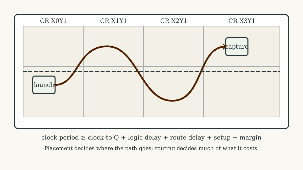
Use Clock Regions As Physical Resource Boundaries
AMD UltraScale architecture divides the device into rows and columns of clock regions. Each region contains logic, DSP, block RAM, interconnect, a horizontal clock spine, and associated leaf clocking. Vertical and horizontal resources connect or isolate those regions.
The official UG572 clocking overview specifies region dimensions, clock roots, distribution tracks, and segmented boundaries. That structure determines how clocks reach every placed resource.
Fit The Long Path Inside The Setup Budget
A launch register changes state after a clock edge. Combinational logic and routed nets carry its output, and the capture register needs a stable value before the next active edge.
The central setup budget reads:
Tperiod ≥ Tcq + Tlogic + Troute + Tsetup + margin
The full tool calculation adds clock arrival, skew, uncertainty, waveform relationships, path exceptions, and corner-specific delay models. Positive setup slack records the remaining margin; negative slack records the amount of required repair.
Protect The Short Path With A Hold Budget
Hold analysis constrains minimum delay so a new value reaches the capture register after the value belonging to the same edge has safely settled.
Extra data-path delay can repair hold while consuming setup margin, and clock skew can help one check while hurting the other. Timing closure therefore solves a coupled spatial problem across both maximum and minimum delay.
Ask The Exact Timing Question With Constraints
Timing tools need primary and generated clocks, input and output delays, clock-domain relationships, and justified exceptions. A complete constraint set gives every relevant path a defined requirement and a meaningful result.
AMD’s current four-step timing-constraint guidance begins with clock waveforms and I/O delays, then reviews asynchronous or exclusive clock relationships. Architectural intent must justify every false path and multicycle path.
Let Routed Interconnect Reveal The Dominant Delay
Synthesis sees logic and estimated nets; implementation chooses actual sites and routes. Distance, high-fanout replication, regional crossings, and congestion can make a low-logic path dominate the timing budget.
AMD’s congestion guidance connects routing congestion directly to long net delays and difficult timing closure. Routed timing supplies the final path result.
Iterate Through The Architecture Until Every Path Closes
Logic restructuring, pipelining, retiming, resource selection, fanout reduction, placement, floorplanning, clocking, congestion relief, and corrected requirements each address a different physical cause.
The UG949 closure process prioritizes high-impact clocking and worst-domain violations before isolated path work. Each timing report directs the next architectural change.
Map Cartilage Regions Onto Physical Resources
A spatially reconfigurable region must fit within placement, routing, clocking, event, and configuration budgets. Region ownership expresses locality, and implementation converts that locality into measured route and clock results.
Cartilage browser models, RTL, exact installs, and QFG runs define the logical architecture. Physical implementation adds timing closure. The next chapter descends into the route itself—the “metal wire”—with its layer, direction, resistance, capacitance, and capacity.