The Rendered Artifact
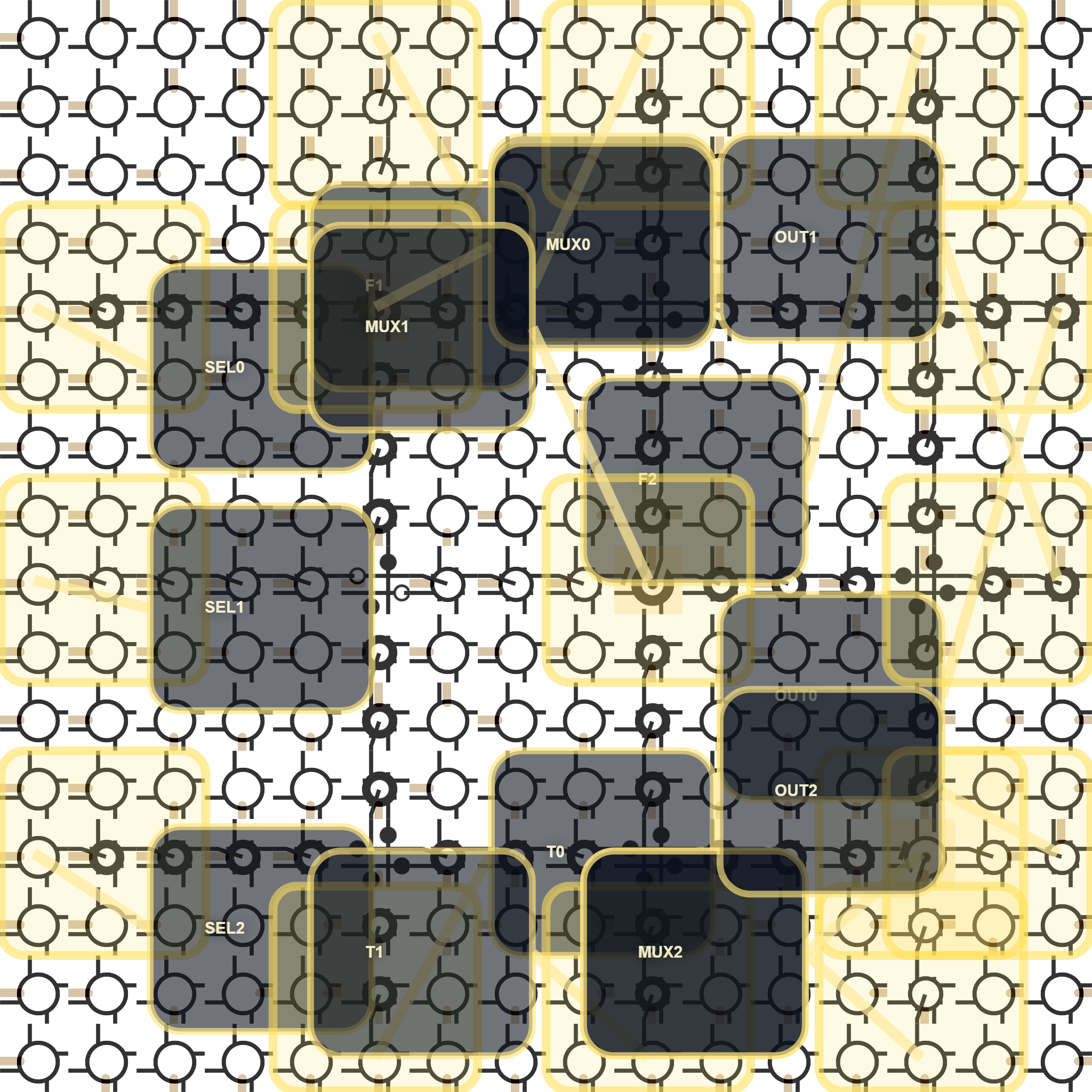
The Circuit
Each lane is a plain 2:1 mux. The lane reads one selector, one false-side value, and one true-side value:
OUT0 = SEL0 ? T0 : F0
OUT1 = SEL1 ? T1 : F1
OUT2 = SEL2 ? T2 : F2
The three lanes are independent. The value of the example is not arithmetic depth; it is that the inputs and outputs cross the fabric boundary through the external transaction path and are checked against the manifest.
Driven Inputs
The manifest drove nine boundary values:
SEL0@left4=1   F0@top5=0   T0@bottom5=1
SEL1@left8=0   F1@top9=1   T1@bottom9=1
SEL2@left12=1  F2@top13=1  T2@bottom13=0
With those values, the expected outputs are:
OUT0@right4=1
OUT1@right8=1
OUT2@right12=0
Verification Result
The generated surface assertion passed:
expected OUT0@right4=1, OUT1@right8=1, OUT2@right12=0
observed OUT0=1, OUT1=1, OUT2=0
The run used 160 fabric cycles in manifest drive mode. The first edge readback already showed active left-edge selector positions, and the final readback showed the asserted right-edge outputs.
Why This Replaces The Sketches
The earlier full-adder and PC-stepper renders are useful visual placement sketches, but they should not be presented as checked working fabric examples until they have the same kind of edge-surface proof.
This mux-lanes render is intentionally smaller. Its claim is narrower and stronger: driven inputs enter through fabric surfaces, local mux islands select values, and the observed outputs match the manifest.
Render Notes
The rendered lattice is 16x16 cells. The PNG is 2048x2048 pixels. The source manifest is cartilage-grid-rs/examples/external-mux-lanes.surface.qfg.
The labels and translucent regions are human reading aids. The underlying cell-role alphabet is decoded in the Cartilage Visual Language article.