The Compute Claim
The driver does not compute the arithmetic answer. It seeds the browser fabric with primitive Cartilage cell bodies, stages sparse boundary-metal writes for one QFG frame, advances the fabric, and reads the external edge surface.
The measured run is not the 525,568-cycle native reconfiguration proof. The adder body is installed as the initial QFG seed before the measured compute run begins. The claim here is narrower and easier to inspect: an existing Cartilage body receives input bits at its boundary and computes the visible result through its cell state.
Callout Video
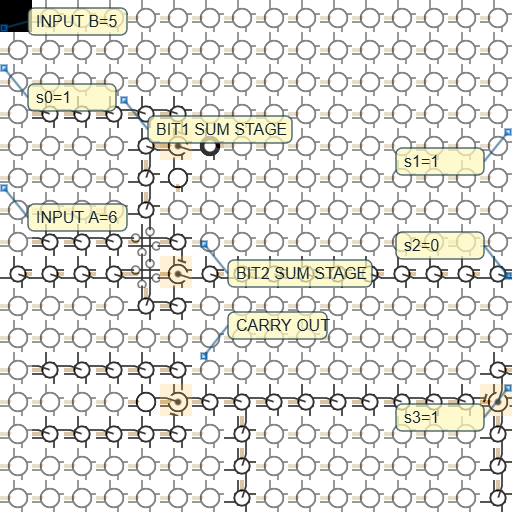
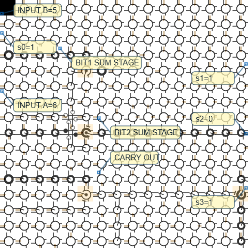
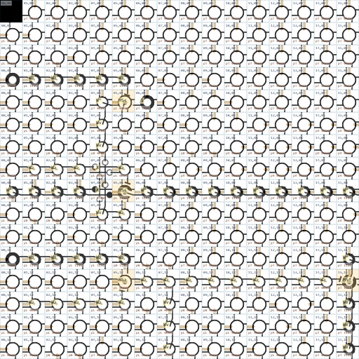
Final State

INPUT_A=6, INPUT_B=5, BIT1_SUM_STAGE, BIT2_SUM_STAGE, CARRY_OUT, and the four result ports.The Artifact Bundle
The files are preserved under cartilage/codex5.5/. These links point to concrete files, not directory listings.
- quadflow-use-static3-a6-b5-fullframes.md - package note and reproduction commands.
- use-static3-a6-b5.qfg - exact QFG source streamed into the browser fabric.
- use-static3-a6-b5-callouts.surface.qfg - sparse publication callout labels.
- use-static3-a6-b5-run-report.md - raw lockstep run report for the coordinate render.
- use-static3-a6-b5-callouts-run-report.md - raw lockstep run report for the callout render.
- quadflow-use-static3-a6-b5-fullframes-manifest.json - frame list, hashes, and verification metadata for the plain render.
- quadflow-use-static3-a6-b5-fullframes-callouts-manifest.json - frame list, hashes, and verification metadata for the callout render.
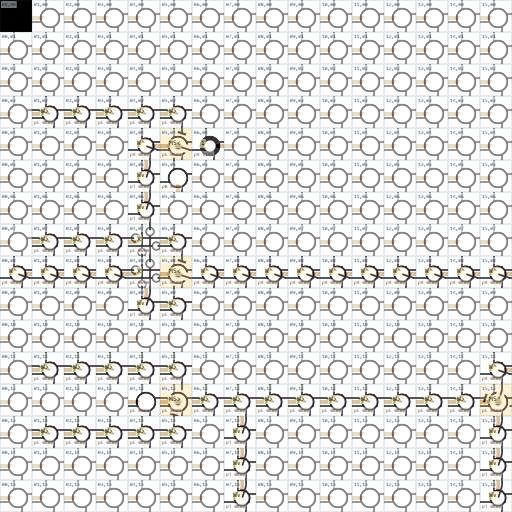
Frame Coverage
The computation ran for 256 fabric update cycles. The capture contains 257 PNGs because it includes cycle 0, then every committed state after cycles 1 through 256. The MP4 frame count was verified as 257 frames at 512x512 and 30 fps.
Representative direct frame links:
The manifests contain the complete 257-frame lists and SHA-256 hashes for both frame sequences.
Boundary Inputs
The generated QFG contains 469 seed cells and one operand frame. It contains no embedded expect lines. That matters because the result is read back from the external edge surface, not from expected-output clauses inside the input stream.
The high-level frame comment in the QFG source is:
# a=6 b=5 -> 1101
frame 256
boundary left 7 gnd parent left
boundary left 13 gnd parent left
boundary left 3 pwr parent left
boundary right 8 pwr parent right
boundary left 11 pwr parent left
boundary left 23 pwr parent left
boundary left 27 pwr parent left
boundary left 17 gnd parent left
boundary left 22 gnd parent left
boundary left 25 gnd parent left
boundary left 41 pwr parent left
boundary left 45 pwr parent left
boundary left 35 pwr parent left
boundary left 40 pwr parent left
boundary left 43 pwr parent left
For a = 6, the operand bits are a0=0, a1=1, a2=1. For b = 5, they are b0=1, b1=0, b2=1. Those become the pwr and gnd boundary lines in the QFG frame.
Output Readout
The run report says the final active boundary outputs were at left edge position 8, right edge position 16, and right edge position 48. The documented output decode is:
left[8]       -> s0 = 1
right.sl[16]  -> s1 = 1
right.sl[34]  -> s2 = 0
right.sl[48]  -> s3 = 1
So the emitted result order is s0 s1 s2 s3 = 1101. Interpreted in ordinary display order, that is 1011, decimal 11.
Callouts Are Not Computation
The callout layer is drawn after the fabric state is rendered. It labels input regions, output ports, and core adder regions for explanation. It does not alter any cell, edge, Sinew metal, Intersin value, QFG frame, or result bit.
mark 0 23 INPUT_A=6
mark 0 3 INPUT_B=5
mark 15 12 BIT1_SUM_STAGE
mark 25 30 BIT2_SUM_STAGE
mark 25 44 CARRY_OUT
mark 0 8 s0=1
mark 63 16 s1=1
mark 63 34 s2=0
mark 63 48 s3=1
Tradeoff
This is still a small computation, and the adder body is pre-generated before the measured run starts. The gain is that the example is inspectable end to end: source QFG, boundary frame, run report, manifests, first and final frames, videos, and every committed PNG state are all part of the published artifact package.