The Rendered Artifact
The Stepper Function
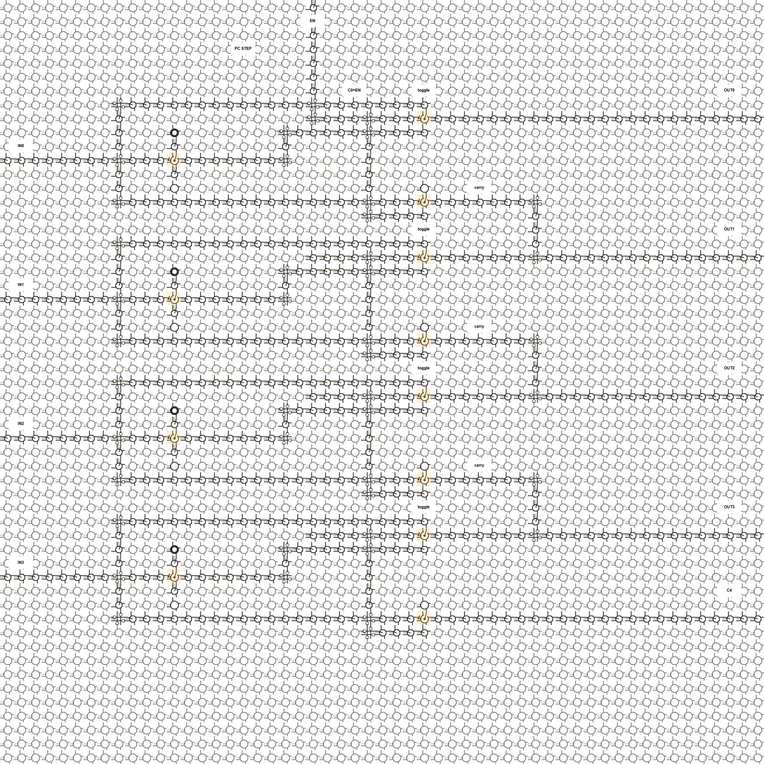
Each bit slice receives one input bit and one carry bit. The carry seed is C[0] = ENABLE, so the circuit increments only when enable is asserted.
OUT[i]    = IN[i] xor C[i]
C[i + 1] = IN[i] and C[i]
C[0]     = ENABLE
When ENABLE is zero, the first carry is zero and every output bit copies its input. When ENABLE is one, the carry ripple performs the ordinary increment-by-one operation.
MUX Island Decomposition
The Cartilage placement uses mux-friendly local logic islands. Each bit slice is decomposed into a local inversion island, an output toggle island, and a carry island:
notIN[i] = IN[i] ? 0 : 1
OUT[i]   = C[i] ? notIN[i] : IN[i]
C[i + 1] = IN[i] ? C[i] : 0
The repeated structure is the point of the render. It is easier to inspect than a single adder because the four slices show the same local rule repeated with a visible carry chain.
How To Read The Routes
ENABLE enters from the top edge and seeds C0. IN0 through IN3 enter from the left edge. OUT0 through OUT3 leave to the right edge, and the final overflow carry C4 is also routed to the right edge.
The sea around the active logic is mostly constant-zero cells. It is intentionally spacious so the repeated slice structure, local toggle islands, carry islands, intersections, and edge routes stay readable.
Data I/O Is Ordinary Fabric Routing
The data inputs and outputs are ordinary metal adjacency through neighboring fabric cells. Reconfiguration-port cells are not used for these data paths.
That distinction is part of the Cartilage model: reconfiguration ports change fabric state, while this screenshot shows a configured control/arithmetic datapath carrying runtime data through local wires, intersections, constants, and MUX behavior.
Render Notes
The rendered lattice is 55x55 cells. The PNG is 3080x3080 pixels. It is a cycle-zero initialized-cell schematic with 19 semantic labels.
The labels are callouts for the human reader, not extra tile roles. The cell vocabulary is the same Cartilage render alphabet decoded in the Cartilage Visual Language article.