The Rendered Artifact
The Boolean Function
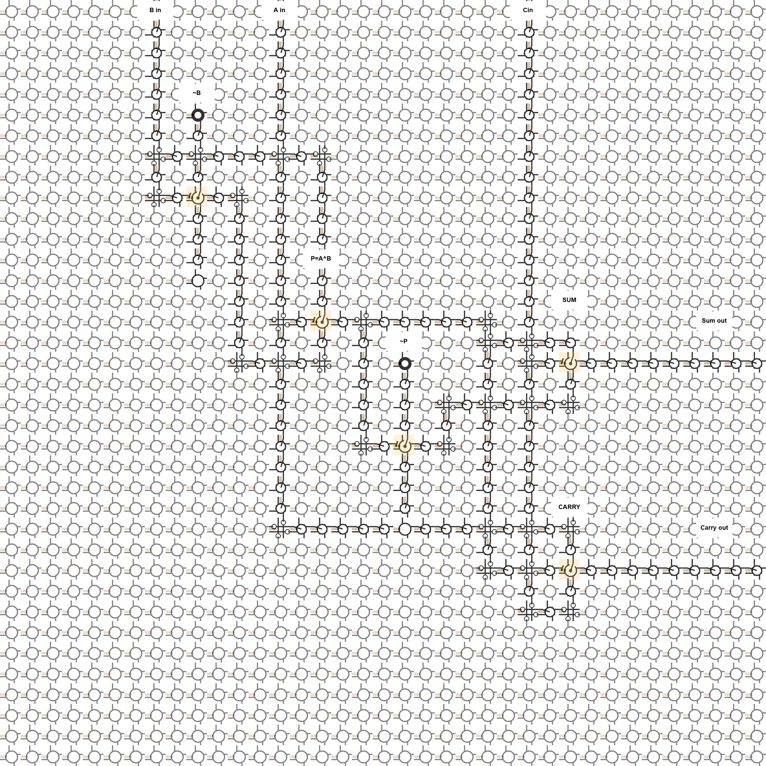
The placed circuit is the extracted full-adder function, expressed as mux-friendly local equations:
notB  = B ? 0 : 1
P     = A ? notB : B
notP  = P ? 0 : 1
SUM   = Cin ? notP : P
CARRY = P ? Cin : A
Equivalently, P is A xor B, SUM is Cin xor P, and CARRY is (A and B) or (Cin and (A xor B)).
Data I/O Is Not Reconfiguration I/O
The top-edge inputs and right-edge outputs are ordinary data routes through neighboring fabric cells. They are not reconfiguration-port cells.
That distinction matters in Cartilage. Reconfiguration ports are for changing fabric state. This drawing is showing a configured arithmetic circuit: data enters over wire cells, flows through local MUX islands, and exits over wire cells.
Why The Islands Are Spread Out
The fabric is intentionally over-provisioned. Most cells remain in the constant-zero sea so the labels have readable space and each logic island can be inspected without the picture turning into a dense routing block.
The sea is interrupted by the wire cells and intersection cells needed to carry B, A, Cin, P, SUM, and CARRY between islands and to the fabric edge.
Relation To The Hand Sketch
The render is based on the hand-drawn full-adder sheet where B, A, and carry-in enter from the top and SUM plus carry-out leave to the right. It is not an OCR transcription of that photograph.
The published image is the extracted function mapped into available Cartilage cell roles: constants, wires, intersections, and MUX behavior.
Render Notes
The rendered lattice is 37x37 cells. The PNG is 2960x2960 pixels. It is a cycle-zero initialized-cell schematic with ten semantic labels.
Read the white label boxes as human callouts. The underlying fabric vocabulary is still the same Cartilage cell-role alphabet explained in the Cartilage Visual Language article.