Install A Complete Workbench In One Command
On a current Debian or Ubuntu system, install the compiler, waveform viewer, and build driver from the distribution packages:
sudo apt update
sudo apt install iverilog gtkwave make
Distribution releases carry different package versions, so record the versions that will execute the lab:
iverilog -V
vvp -V
gtkwave --version
make --version
The official Icarus Verilog documentation covers the compiler and runtime, while the GTKWave documentation covers signal inspection. When a design needs a newer language feature, pin a known tool release or reproducible bundle so every run uses the same environment.
See The Circuit And Execute Its HDL
Use the current Logisim-evolution release for your operating system to keep Boolean structure visible beside the simulator. Distribution repositories may also carry it under release-specific package names.
Logisim exposes the counter’s gates, storage, and wires. Icarus executes the Verilog or SystemVerilog description under precise simulation semantics. Rebuilding the same counter both ways joins visible structure with automated, repeatable behavior.
Run The Complete Four-File Counter Lab
Four focused files give the counter a design, an environment, a repeatable command, and a clear result:
counter.vdefines the parameterized four-bit circuit;counter_tb.vsupplies the clock, reset, checks, and VCD output;Makefilecaptures the exact compile and run commands; andREADME.mdrecords the expected terminal result.
Place the files in one directory, open a shell there, and run:
makeThe Makefile exposes the two stages directly:
iverilog -g2012 -Wall -s counter_tb \
  -o build/counter_tb counter.v counter_tb.v
vvp build/counter_tb
The completed run ends with:
PASS: reset, five updates, and four-bit wrap verifiedThat line means the simulator observed reset holding the count at zero, five enabled rising edges producing five increments, and eleven more increments wrapping the four-bit value back to zero.
Read The Testbench As A Timed System
The testbench asserts reset, waits for two positive clock edges, and releases reset on a negative edge so the control settles before the next active edge. It then observes the count after five more positive edges. A short #1 delay allows nonblocking register updates to settle before each check.
Case inequality, !==, treats an unknown x or high-impedance z as a mismatch. On failure, $fatal stops the run and prints both expected and observed values. The testbench therefore decides the result consistently on every machine.
The waveform explains the timing behind that result. Open it with:
make waveOr run gtkwave counter.vcd directly. Add clk, reset, and count to the view, set count to binary or unsigned decimal, and trace each state change from the first rising edge after reset.
Extend The Workbench Through A C++ Host
Verilator translates synthesizable Verilog or SystemVerilog into a compiled C++ or SystemC model. That execution model supports fast simulation, linting, and direct integration with software test harnesses.
Install the distribution package and lint the counter:
sudo apt install verilator
verilator --version
verilator --lint-only -Wall counter.v
A C++ simulation host constructs the model, drives inputs, advances time, evaluates the design, and inspects outputs. This explicit interface lets a hardware model participate directly in a larger software system. The official Verilator guide provides the next steps.
Turn Each Prediction Into An Executable Check
Erik J. Larson’s The Myth of Artificial Intelligence, informed guesses about codebreaking at Bletchley Park, probability, and “first a guess, then testing veracity” all point to the same engineering habit: formulate the expected result before running the tool.
For this counter, reset dominates, count advances only at rising edges, and four bits wrap after sixteen states. The testbench encodes those expectations, while the waveform reveals the timing behind every transition.
Intuition chooses a productive test sequence. Automated checks make it repeatable, and the recorded signal trace turns each result into an explanation you can inspect.
Carry The Checked RTL Into FPGA Implementation
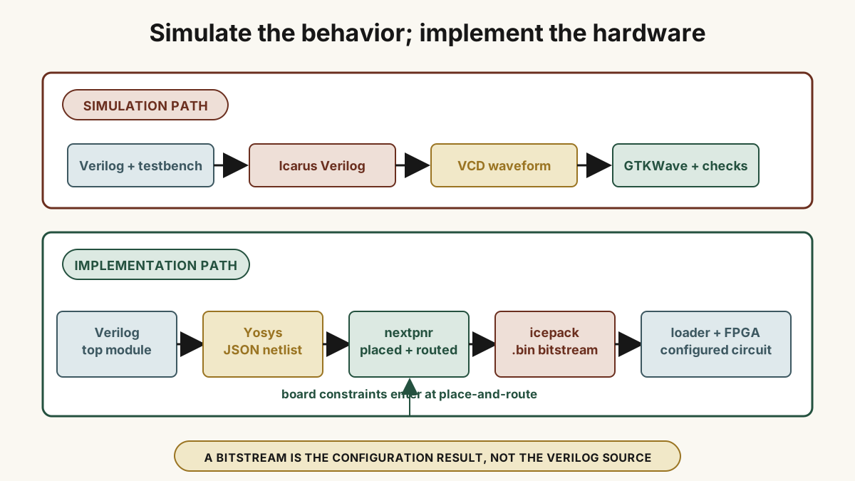
The workbench delivers executable RTL behavior, automated checks, and a signal trace. Chapter 5 organizes the design, testbench, selected top, and board constraints; chapter 7 carries those files through synthesis, FPGA resource selection, pin assignment, place-and-route, timing, bitstream generation, and board programming.
The same division scales from this four-bit counter to pipelined datapaths, peripheral controllers, and hardware models embedded in larger software systems.